One challenge of adapting the 486 bus protocol to the 286 bus protocol is that the 286 outputs the address of the next bus cycle while the data of the previous bus cycle is still happening. The address is guaranteed to be valid half a bus clock before the "official" begin of the cycle that consists of two bus clocks (with the data being transferred at the end of the second clock). So the time from the address bits being stable to the time the data needs to be on the data bits is 2.5 bus clocks, whereas such a cycle can happen every 2 bus clocks. The 486 doesn't have the concept of "forecasting" the next address, although the 386 and the Pentium processors have it as optional feature.
The 16-bit ISA specification for 0WS memory read/writes (exectly what we are after here) makes use of the 286 feature to give advance address information: The LA17-LA23 pins on the 16-bit expansion part of the ISA connector present the address bits as output by the processor with minimal delay. That means these bits are not valid during the complete bus transaction, but they are valid in advance to MEMR/MEMW. A proper 16-bit ISA memory card should use LA16-LA23 to detect whether the currently addressed 128KB block maps to this card, and assert /MEMCS16 to inform the chipset that the bus is able to perform a 16-bit cycle. The crtitical path for performing 16-bit 0WS cycles is:
- The bus provides the address
- The card assert /MEMCS16, to indicate that it is 16-bit capable, in case a memory cycle is going to happen
- The chipset decides whether it should perform a single 16-bit cycle or split the cycle into two 8-bit cycles and provides A0 and SBHE
- The chipset signals /MEMR or /MEMW
- The card detects that a memory cycle is indeed going to happen and asserts /0WS
- The chipset recognizes /0WS and terminates the cycle as soon as possible
Having the extra 0.5 clocks at the start of the cycle for detecting 16-bit capability relaxes timing constraints on this path and made 0WS cycle possible in the AT or XT286. A simple 486-to-286 bus protocol adaption implementation might want to simplify stuff by just stretching out the minimal cycle time to 3 cycles, with the whole first cycle just "forecasting" the address. This would explain one of the two extra wait states you are experiencing.
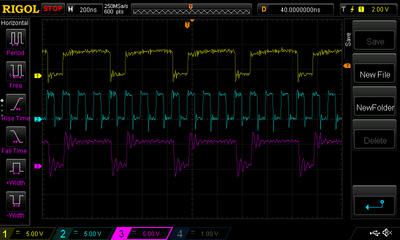
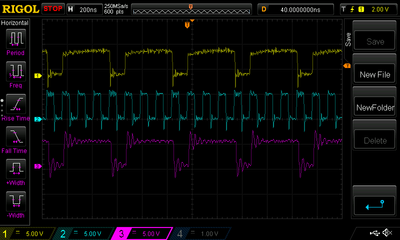
If you are after finding out exactly where the two cycles "get lost" that slow down your ISA implementation from 7.5MB/s to 3.8MB/s, you really would need to scope the 486 /ADS pin (which actually starts the cycle on the 486 side), the /MEMW pin (which indicates the write to the ISA bus) and the 486 /RDY pin (which tells the 486 that the cycle has been fully served). But knowing where the time gets lost is just to address your curiosity (if there is any), and likely you still won't be able to speed things up.