VOGONS


First post, by Socket3

User metadata
Rank Oldbie
Rank
Oldbie

Hello everyone.

I got a hold of a few nice 386 motherboards a while a go, but it seems all of them have defects. Two of them in particular have shorted 12v or 5v rails - I didn't even attempt to power them on. One of these boards has loads of 10uf tantalum capacitors... and all of them test as shorted with all 3 of my multimeters...

This is the 5v rail - my multimeter beeps and the display shows 30 (witch I presume is miliohms).

shorted 5v.jpg
Filename
shorted 5v.jpg
File size
1.86 MiB
Views
1583 views
File license
CC-BY-4.0

This is one of the shorted tantalum caps. If I remember correctly, they're 16v 10uf. ALL of them seem to be shorted...

shorted tantalums.jpg
Filename
shorted tantalums.jpg
File size
1.25 MiB
Views
1583 views
File license
CC-BY-4.0

Is it possible they have all gone bad or am I doing something wrong?

Last edited by Socket3 on 2023-01-22, 22:15. Edited 1 time in total.

Reply 2 of 18, by Socket3

User metadata
Rank Oldbie
Rank
Oldbie
paradigital wrote on 2023-01-22, 22:14:

If you are testing them in circuit then it’s entirely possible (and to be honest, more plausible) that something else is shorting to ground.

How would I go about finding the source of the short circuit?

Reply 3 of 18, by mkarcher

User metadata
Rank l33t
Rank
l33t

Probably one of the capacitors is short, and all of them are in parallel (on the +5V line). Your meter is in diode/continuity mode. The display is "millivolts drop at a unspecified current aroung 1 to 10 mA", and is intended to show the forward voltage of diodes. You can try to find the cap that shows the lowest value. That one is likely the shorted cap, because at the other caps, you measure the resistance of the 5V/GND planes to the shorted cap as well as the shorted cap itself.

Reply 4 of 18, by pentiumspeed

User metadata
Rank l33t
Rank
l33t

Only way is thermal camera and lab power supply with 1 ohm 10w resistor in series and look for a warmest tantalum capacitor which means the source of short.

Cheers,

Great Northern aka Canada.

Reply 5 of 18, by aaronkatrini

User metadata
Rank Member
Rank
Member

Just change them all or see the what happens:
https://www.amibay.com/threads/quick-video-of … 2/#post-2445635

Most likely one a few are shorted, but finding it can be difficult and just go the safe route and change them all because eventually all of them will go short.

Reply 6 of 18, by Ozzuneoj

User metadata
Rank l33t
Rank
l33t

If you can use the methods posted above to figure out which one is shorted, just replace it with whatever cap you have on hand with the same uf and voltage. This will at least let you know if the rest of the board works. If you want to be sure it has a properly specced cap later, swap it out with something more appropriate once you have them on hand.

I would not change all of the caps just because they are tantalums however. The percentage of tantalums that fail is incredibly small, and if they do not fail now they will likely last longer than any aluminum electrolytics you would be replacing them with.

I have had hundreds of vintage cards, boards and computers pass through my hands over the years and I've seen a lot of tantalums on them, and I have only had one explode (on a Trident ISA VGA card from the early 1990s). I have seen maybe two fail open or closed without causing any explosion or smoke. Those were on devices from the late 80s that had not been used in decades. One was in a GRiDcase 386 laptop internal (removable) power supply, the other was on a brand new in box Everex EGA card from the mid to late 80s. Both problems occurred the first time the device was powered on, the faulty caps were replaced and the devices have had no problems with other tantalums.

Remember, unless you're an absolute professional at PCB soldering, every part you work on increases your chances of damaging the device.

Last edited by Ozzuneoj on 2023-01-23, 08:28. Edited 1 time in total.

Now for some blitting from the back buffer.

Reply 7 of 18, by Jo22

User metadata
Rank l33t++
Rank
l33t++
paradigital wrote on 2023-01-22, 22:14:

If you are testing them in circuit then it’s entirely possible (and to be honest, more plausible) that something else is shorting to ground.

+1

In-Circuit Testing never really works. In practice, at least one leg must be lifted.
However, the most straightforward approach would be to simply desolder them all and check them with a capacity tester.
Alternatively, short them for a moment (to discharge them) and then charge them with a battery, then check with a voltmeter/ampéremeter.

Edit: @everyone If you can, get hold of an old style analogue meter with a mechanical scale as a backup meter.
They are sometimes easier to read, depending on the application - for example, if a value increases/decreases.
That's because the needle doesn't react as erratic as a digital display.
It also swings back and forth between a minimum/maximum,
so you have a visual representation of a "window" in which the values/measurements move in.

Of course, this is only a quick'n'dirty checkup. It also says something about its DC behavior only.
AC and RF are more tricky. Especially RF. Back in the early days of radio, sometimes capacitors -err- "condensers"
looked fine as far as DC was considered, but simultanously failed miserably in an RF application.
Anyway, RF equals voodoo, anyway. So it's a different story. 😉

"Time, it seems, doesn't flow. For some it's fast, for some it's slow.
In what to one race is no time at all, another race can rise and fall..." - The Minstrel

//My video channel//

Reply 8 of 18, by Socket3

User metadata
Rank Oldbie
Rank
Oldbie
Ozzuneoj wrote on 2023-01-23, 02:50:

If you can use the methods posted above to figure out which one is shorted, just replace it with whatever cap you have on hand with the same uf and voltage. This will at least let you know if the rest of the board works. If you want to be sure it has a properly specced cap later, swap it out with something more appropriate once you have them on hand.

Sounds like a pain in the butt and will probably wear the board out a bit - BUT - it also sounds like the only sure-fire way to find the short... thank you for your advice...

One question tough... would pulling the caps out one by one and testing them in a component tester help find the short? I'd rather not solder in replacements unless they're the correct type...

Ozzuneoj wrote on 2023-01-23, 02:50:

I would not change all of the caps just because they are tantalums however. The percentage of tantalums that fail is incredibly small, and if they do not fail now they will likely last longer than any aluminum electrolytics you would be replacing them with.

I have had hundreds of vintage cards, boards and computers pass through my hands over the years and I've seen a lot of tantalums on them, and I have only had one explode (on a Trident ISA VGA card from the early 1990s). I have seen maybe two fail open or closed without causing any explosion or smoke. Those were on devices from the late 80s that had not been used in decades. One was in a GRiDcase 386 laptop internal (removable) power supply, the other was on a brand new in box Everex EGA card from the mid to late 80s. Both problems occurred the first time the device was powered on, the faulty caps were replaced and the devices have had no problems with other tantalums.

That has been my experience with tantalums as well. In fact I've taken to replacing SMD aluminum caps on video cards and some manboards with tantalums or ceramic caps whenever possible.

As for exploding caps:

ifhedies.jpg
Filename
ifhedies.jpg
File size
276.56 KiB
Views
1426 views
File license
GPL-2.0-or-later
Ozzuneoj wrote on 2023-01-23, 02:50:

Remember, unless you're an absolute professional at PCB soldering, every part you work on increases your chances of damaging the device.

I wouldn't say I'm a professional, but I do have over 15 years of practice in my free time. I'm pretty confident in my soldering skills, and I've managed to put together a decent set of soldering and desoldering tools to aid in everything from scavenge parts off vintage boards to SMD and BGA repair. Still, like I mentioned above, I'd rather not solder in a replacement part then have to desolder it later - I'll try removing the caps one by one and testing them out of circuit in my component tester.

Jo22 wrote on 2023-01-23, 06:40:
+1 […]
Show full quote
paradigital wrote on 2023-01-22, 22:14:

If you are testing them in circuit then it’s entirely possible (and to be honest, more plausible) that something else is shorting to ground.

+1

In-Circuit Testing never really works. In practice, at least one leg must be lifted.
However, the most straightforward approach would be to simply desolder them all and check them with a capacity tester.
Alternatively, short them for a moment (to discharge them) and then charge them with a battery, then check with a voltmeter/ampéremeter.

Thank you, I'll try this method first. If I find the shorted cap could I check the +5v rail again? Would it still be shorted if I pull a bad cap off - or will it open if I lift any of the capacitors from the circuit, good or bad?

Jo22 wrote on 2023-01-23, 06:40:
Edit: @everyone If you can, get hold of an old style analogue meter with a mechanical scale as a backup meter. They are sometime […]
Show full quote

Edit: @everyone If you can, get hold of an old style analogue meter with a mechanical scale as a backup meter.
They are sometimes easier to read, depending on the application - for example, if a value increases/decreases.
That's because the needle doesn't react as erratic as a digital display.
It also swings back and forth between a minimum/maximum,
so you have a visual representation of a "window" in which the values/measurements move in.

Of course, this is only a quick'n'dirty checkup. It also says something about its DC behavior only.
AC and RF are more tricky. Especially RF. Back in the early days of radio, sometimes capacitors -err- "condensers"
looked fine as far as DC was considered, but simultanously failed miserably in an RF application.
Anyway, RF equals voodoo, anyway. So it's a different story. 😉

I've been wondering why I often see professionals - especially techs working on vintage electronics like CRTs and tube radios / apms - use these analog meters. I'll try to get a hold of a few working units for myself. An osciloscope is also on my shopping list, but I want to buy something that works well and doesn't break the bank.

Thank you everyone for your suggestions!

Reply 9 of 18, by wbahnassi

User metadata
Rank Member
Rank
Member

Voltage injection with a heat camera is the fastest way to detect the source of the issue without desoldering anything yet.
Short of that, it's an adventure of exploration. And it might not be any of the capacitors either, and they are victims to a short by something else (e.g. a diode, a transistor, or even an IC chip) on the same line. Start by looking for any component on the line that looks off (bulged, discolored, cracked). Then desolder it off the board, then test for the short again using continuity mode of your multimeter. If the component you extracted was the source of the problem then the short will be gone. Start putting back everything else you removed and make sure the short doesn't come back. Otherwise you might have found another source of the short (more than one malfunctioning components).
Finally once your mobo is short-free, check to make sure all fuses/0-ohm resistors are continuous. Those often blow when a short happens. Replace as needed. Then you can safely give the mobo a try 🙂

Reply 10 of 18, by Deunan

User metadata
Rank Oldbie
Rank
Oldbie

Old farts use analog meters because they got used to them, and it looks cooler on YT videos. There is no advantage to having analog meter these days unless you are comparing a decent analog instrument to some crappy digital meter based on ICL7106/07 clone with absolute minimum of other parts and all carbon resistors. With leads that are 99% PVC and 3 tiny strands of copper that will crack soon anyway.

A good digitial meter, with good leads - not even talking about anything bench, a handheld Brymen for example - will help you out. It'll have enough resolution and low noise to tell you where the short is at, or close to it. You just look for the lowest DC resisitance testing each cap. This is not 100% perfect method due to low testing current so nearby parts will show similar results, but at least you get to desolder 2 or maybe 3 capacitors, not all of them. You will have to learn to repeat the measurements and develop a sense of what is a true reding and what is poor probe contact - but it's not rocket science. And you can build a higher current tester if you wish on your own.

That being said, a good rule of thumb is tantalum cap should be rated at 2x expected voltage for some peace of mind. So 10V cap should be good for 5V but if you find more than 1 shorted (or another one blows up) then replace all. Could be a bad batch or some mobo-specific damage (vibrations that cracked all of them, etc). 12V lines should have 25V caps and often use 16V - these go bang pretty often. Replace all if you can. You can go one-by-one but do not be surprised to see the remaining ones blow up after several quiet power-ups, it's just how it is.

And last thing, a resistance of some few ohms on 5V bus is not always a short. Could be the device you are testing is acually pulling more than an amp of current on its own. Keep that in mind. A short is usually well below 1 ohm, in which case there will be fireworks when powering up - this does arguably speed up finding the broken parts but can cause damage to PCB traces.

EDIT: Words. Brain slow today.

Reply 11 of 18, by Jo22

User metadata
Rank l33t++
Rank
l33t++
Deunan wrote on 2023-01-23, 12:18:

Old farts use analog meters because they got used to them, and it looks cooler on YT videos.

This is respectles, I think. And a bit snobby. I know some of these personally. Some of those socalled "old farts", especially radio amateurs, were pioneers in the 1970s when the socalled "computer hobbyists" or "computer enthusiasts" developed machines in the style of the IMSAI 8080 or Altair 8800.

Just because you prefer digital multimeters doesn't mean that other types of instruments are obsolete.
Personally, I think that digital multimeters with a virtual analogue instrument would sell especially well for high prices.
Just look at nowadays smartwaches with digital analogue faces.
The clock faces/backgrounds are an entire market on their own.

Deunan wrote:

There is no advantage to having analog meter these days unless you are comparing a decent analog instrument to some crappy digital meter based on ICL7106/07 clone with absolute minimum of other parts and all carbon resistors. With leads that are 99% PVC and 3 tiny strands of copper that will crack soon anyway.

I don't mean to be rude, but did you actually read my post and my explanation?
It's not about the technology as such, but the visual representation.
A bog standard digital multimeter has numerical representation only.
A classic multimeter has a small latency which results in a smoother movement.

Anyway, I didn't encourage anyone to replace a digital multimeter by a vintage model.
I merely said that the analogue, scale based models are useful for certain tasks.

Another useful feature is, that certain models operate completely passive (others use batteries, too.)

The passiveness is useful if the application is very sensitive to voltage.
The stereotypical yellow/blue digital multimeters do probe with a 9v source.
Sure, it's current-limited. But the voltage alone might be enough to damage highly sensitive parts like old DRAM, germanium diodes, early transistors.

Back in the day, high-impedance tube voltmeters were used, too.
They were useful for certain tasks, because they didn't cause an electrical burden to the test application.
In other words, they didn't interfere with its function.
They didn't cause a voltage drop during measuring.
Like an oscilloscope, they were high-impedance and could work with live equipment. TVs, radios, etc.
That being said, these tube voltmeters aren't needed more as much as in the past.
They're still highly accurate, though.

"Time, it seems, doesn't flow. For some it's fast, for some it's slow.
In what to one race is no time at all, another race can rise and fall..." - The Minstrel

//My video channel//

Reply 12 of 18, by Deunan

User metadata
Rank Oldbie
Rank
Oldbie

If anything I wrote was rude, I'm sorry, it was not my intention to offend. I'm merely being sarcastic, perhaps a bit too much? But I do stand by what I've said.

Jo22 wrote on 2023-01-23, 13:32:

This is respectles, I think. And a bit snobby. I know some of these personally. Some of those socalled "old farts", especially radio amateurs, were pioneers in the 1970s when the socalled "computer hobbyists" or "computer enthusiasts" developed machines in the style of the IMSAI 8080 or Altair 8800.

I don't think that is relevant here. First computers were made with relays, then vacuum tubes, then individual transistors. I dare say both the tech and the test equipment have evolved a tiny bit since then. If someone prefers to use old, analog meters because - and this is obvious from your explanation too - they are old and that is what they're used to, fine, let them. But to actually seriously suggest that anything but the highest end analog meters are any match for modern digital ones is... dubious, at best.

Jo22 wrote on 2023-01-23, 13:32:
Just because you prefer digital multimeters doesn't mean that other types of instruments are obsolete. Personally, I think that […]
Show full quote

Just because you prefer digital multimeters doesn't mean that other types of instruments are obsolete.
Personally, I think that digital multimeters with a virtual analogue instrument would sell especially well for high prices.
Just look at nowadays smartwaches with digital analogue faces.
The clock faces/backgrounds are an entire market on their own.

You have a fondness for analog stuff. So do I in fact. But do not confuse your fondness for usefulness, and certainly make sure any advice you offer take that fondness into account. As for your idea of mixing a bulky, fragile analog indicator into modern, rugged handheld... Let's just say I will stand corrected if and when you'll make some money on that scheme. Yes, there is a huge market with all kinds of idiots with entirely too much money on their hands - be it watches, audio equipment made with unicorn blood, or "sport" cars. But I am at least hoping actual engineers will not fall for it.

Jo22 wrote on 2023-01-23, 13:32:
I don't mean to be rude, but did you actually read my post and my explanation? It's not about the technology as such, but the vi […]
Show full quote

I don't mean to be rude, but did you actually read my post and my explanation?
It's not about the technology as such, but the visual representation.
A bog standard digital multimeter has numerical representation only.
A classic multimeter has a small latency which results in a smoother movement.

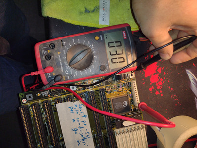
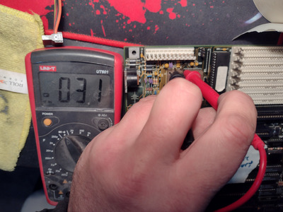
I did read it, and now I suspect you have never held a modern meter in your hands. Or just the really cheap 1$ wonders from supermarkets. Ever heard of a bar graph? Refreshed at, at least, 10 times/s, except not susceptible to orientation, vibrations or parallax effect. And that's for the cheaper models, bit more expensive meter will have actual readouts at 10/s and the graph at 3-10x that. With at least 3.5 digits of resolution if not actual accuracy. Which analog meter, that is not a heavy bench (and possibly AC powered) model, offers miliohm resolution? Because we are still talking about finding shorted tantalum capacitors on a motherboard, not how to build a tube radio and feel like it's 1920 again - right?

Jo22 wrote on 2023-01-23, 13:32:

(...) Back in the day, high-impedance tube voltmeters were used, too.

I'm going to say that I like tube meters, even more than I like any other tube electronics like radios, TV, or even scopes . I even use - as in, an instrument, not something to just look at - older frequency counter with nixie display, though that's the only tubes it has. I would not, EVER, recommend tube-based devices to anyone, except maybe as a fun toy and/or a prop for YT. But I will stop here, I think I've made my point clear enough, I do not want to argue this any further. If you wish to so, please PM me.

Reply 13 of 18, by Socket3

User metadata
Rank Oldbie
Rank
Oldbie
wbahnassi wrote on 2023-01-23, 12:02:

Voltage injection with a heat camera is the fastest way to detect the source of the issue without desoldering anything yet.

Unfortunately I don't have a thermal camera... I'm planning on buying one, it's on the list - as well as a proper bench power supply (not an ATX PSU rigged to a breadboard populated by diodes and potentiometers), an oscilloscope and a good electronics microscope.

wbahnassi wrote on 2023-01-23, 12:02:

Short of that, it's an adventure of exploration. And it might not be any of the capacitors either, and they are victims to a short by something else (e.g. a diode, a transistor, or even an IC chip) on the same line. Start by looking for any component on the line that looks off (bulged, discolored, cracked). Then desolder it off the board, then test for the short again using continuity mode of your multimeter. If the component you extracted was the source of the problem then the short will be gone. Start putting back everything else you removed and make sure the short doesn't come back. Otherwise you might have found another source of the short (more than one malfunctioning components).
Finally once your mobo is short-free, check to make sure all fuses/0-ohm resistors are continuous. Those often blow when a short happens. Replace as needed. Then you can safely give the mobo a try 🙂

Thanks for the tips! I'll keep all that in mind when I have a go at the board again.Right now I'm slowly packing, testing and inventorying all my retro hardware so I can install a wall and make a dedicated room for them in my garage - but please keep the tips coming, I'll review this thread in its entirety when I'll be able to work on them.

Reply 14 of 18, by Ozzuneoj

User metadata
Rank l33t
Rank
l33t
Socket3 wrote on 2023-01-23, 10:27:
Ozzuneoj wrote on 2023-01-23, 02:50:

If you can use the methods posted above to figure out which one is shorted, just replace it with whatever cap you have on hand with the same uf and voltage. This will at least let you know if the rest of the board works. If you want to be sure it has a properly specced cap later, swap it out with something more appropriate once you have them on hand.

Sounds like a pain in the butt and will probably wear the board out a bit - BUT - it also sounds like the only sure-fire way to find the short... thank you for your advice...

One question tough... would pulling the caps out one by one and testing them in a component tester help find the short? I'd rather not solder in replacements unless they're the correct type...

Hmm... maybe what I said didn't come across the way I intended, as it's actually the quick\simple\lazy way to get the board working. 😁

Someone mentioned a method of checking the caps for slight variations in resistance using the diode tester function. If this actually works then you don't have to pull each and every tantalum. Once you think you have located the bad cap with this method you can just desolder one leg and then test the cap for a short across it's legs. If it is still shorted, then you know it needs replaced. If the short across the other caps is still there, you'll need to continue testing them to find other shorts. Once you have eliminated the shorts by lifting one leg on each cap that you suspect is bad, you can replace them with what you have on hand.

I only mentioned swapping it out with a better cap later if you want the board working now and you have a compatible (but not tantalum) component on hand but would rather have the "perfect" part in there for the long term. Personally, I don't worry about it much. I have swapped shorted tantalums for whatever low-ESR aluminum caps I have in my stash (I bought a ton of different sizes a few years ago from digikey and mouser) just to get them working, and they have worked fine. I wouldn't bother changing them out later for something that more closely operates like a tantalum unless it seemed totally necessary or if I was going for a more collectors-item grade restoration. Small low-esr electrolytic caps didn't exist when a lot of this gear was made, so they would likely have been fine for these uses if they had been available. That said, I'm no engineer.

If you aren't in a rush to get the board working, then by all means hang onto it until you can get the best replacement parts.

Socket3 wrote on 2023-01-23, 10:27:
Ozzuneoj wrote on 2023-01-23, 02:50:

I would not change all of the caps just because they are tantalums however. The percentage of tantalums that fail is incredibly small, and if they do not fail now they will likely last longer than any aluminum electrolytics you would be replacing them with.

I have had hundreds of vintage cards, boards and computers pass through my hands over the years and I've seen a lot of tantalums on them, and I have only had one explode (on a Trident ISA VGA card from the early 1990s). I have seen maybe two fail open or closed without causing any explosion or smoke. Those were on devices from the late 80s that had not been used in decades. One was in a GRiDcase 386 laptop internal (removable) power supply, the other was on a brand new in box Everex EGA card from the mid to late 80s. Both problems occurred the first time the device was powered on, the faulty caps were replaced and the devices have had no problems with other tantalums.

That has been my experience with tantalums as well. In fact I've taken to replacing SMD aluminum caps on video cards and some manboards with tantalums or ceramic caps whenever possible.

Yeah, I tend to have a bit of concern when I power on a really old card with tantalums for the first time, especially if it came from a nasty scrap lot... but I've seen a lot more leaky electrolytics than bad tantalums. So overall, I'm happy to see tantalums on a board because it means I absolutely do not need to recap the entire board, and if anything is bad it will probably be easy to diagnose. I like things that don't degrade over time. Just fail and get it over with so I can replace one part and move on. 🤣 😀

Jo22 wrote on 2023-01-23, 06:40:
Ozzuneoj wrote on 2023-01-23, 02:50:

Remember, unless you're an absolute professional at PCB soldering, every part you work on increases your chances of damaging the device.

I wouldn't say I'm a professional, but I do have over 15 years of practice in my free time. I'm pretty confident in my soldering skills, and I've managed to put together a decent set of soldering and desoldering tools to aid in everything from scavenge parts off vintage boards to SMD and BGA repair. Still, like I mentioned above, I'd rather not solder in a replacement part then have to desolder it later - I'll try removing the caps one by one and testing them out of circuit in my component tester.

Again, I think maybe my suggestion didn't come across the right way. I agree that replacing the same part more than once increases the risk every time. I only mentioned doing it twice if you needed the board working now but wanted it to have a more period-accurate component\look later on. If you aren't impatient or you aren't picky, this is likely not an issue. 😀

Now for some blitting from the back buffer.

Reply 15 of 18, by Socket3

User metadata
Rank Oldbie
Rank
Oldbie
Ozzuneoj wrote on 2023-01-23, 19:29:
Hmm... maybe what I said didn't come across the way I intended, as it's actually the quick\simple\lazy way to get the board work […]
Show full quote
Socket3 wrote on 2023-01-23, 10:27:
Ozzuneoj wrote on 2023-01-23, 02:50:

If you can use the methods posted above to figure out which one is shorted, just replace it with whatever cap you have on hand with the same uf and voltage. This will at least let you know if the rest of the board works. If you want to be sure it has a properly specced cap later, swap it out with something more appropriate once you have them on hand.

Sounds like a pain in the butt and will probably wear the board out a bit - BUT - it also sounds like the only sure-fire way to find the short... thank you for your advice...

One question tough... would pulling the caps out one by one and testing them in a component tester help find the short? I'd rather not solder in replacements unless they're the correct type...

Hmm... maybe what I said didn't come across the way I intended, as it's actually the quick\simple\lazy way to get the board working. 😁

Someone mentioned a method of checking the caps for slight variations in resistance using the diode tester function. If this actually works then you don't have to pull each and every tantalum. Once you think you have located the bad cap with this method you can just desolder one leg and then test the cap for a short across it's legs. If it is still shorted, then you know it needs replaced. If the short across the other caps is still there, you'll need to continue testing them to find other shorts. Once you have eliminated the shorts by lifting one leg on each cap that you suspect is bad, you can replace them with what you have on hand.

I only mentioned swapping it out with a better cap later if you want the board working now and you have a compatible (but not tantalum) component on hand but would rather have the "perfect" part in there for the long term. Personally, I don't worry about it much. I have swapped shorted tantalums for whatever low-ESR aluminum caps I have in my stash (I bought a ton of different sizes a few years ago from digikey and mouser) just to get them working, and they have worked fine. I wouldn't bother changing them out later for something that more closely operates like a tantalum unless it seemed totally necessary or if I was going for a more collectors-item grade restoration. Small low-esr electrolytic caps didn't exist when a lot of this gear was made, so they would likely have been fine for these uses if they had been available. That said, I'm no engineer.

If you aren't in a rush to get the board working, then by all means hang onto it until you can get the best replacement parts.

Socket3 wrote on 2023-01-23, 10:27:
Ozzuneoj wrote on 2023-01-23, 02:50:

I would not change all of the caps just because they are tantalums however. The percentage of tantalums that fail is incredibly small, and if they do not fail now they will likely last longer than any aluminum electrolytics you would be replacing them with.

I have had hundreds of vintage cards, boards and computers pass through my hands over the years and I've seen a lot of tantalums on them, and I have only had one explode (on a Trident ISA VGA card from the early 1990s). I have seen maybe two fail open or closed without causing any explosion or smoke. Those were on devices from the late 80s that had not been used in decades. One was in a GRiDcase 386 laptop internal (removable) power supply, the other was on a brand new in box Everex EGA card from the mid to late 80s. Both problems occurred the first time the device was powered on, the faulty caps were replaced and the devices have had no problems with other tantalums.

That has been my experience with tantalums as well. In fact I've taken to replacing SMD aluminum caps on video cards and some manboards with tantalums or ceramic caps whenever possible.

Yeah, I tend to have a bit of concern when I power on a really old card with tantalums for the first time, especially if it came from a nasty scrap lot... but I've seen a lot more leaky electrolytics than bad tantalums. So overall, I'm happy to see tantalums on a board because it means I absolutely do not need to recap the entire board, and if anything is bad it will probably be easy to diagnose. I like things that don't degrade over time. Just fail and get it over with so I can replace one part and move on. 🤣 😀

Jo22 wrote on 2023-01-23, 06:40:
Ozzuneoj wrote on 2023-01-23, 02:50:

Remember, unless you're an absolute professional at PCB soldering, every part you work on increases your chances of damaging the device.

I wouldn't say I'm a professional, but I do have over 15 years of practice in my free time. I'm pretty confident in my soldering skills, and I've managed to put together a decent set of soldering and desoldering tools to aid in everything from scavenge parts off vintage boards to SMD and BGA repair. Still, like I mentioned above, I'd rather not solder in a replacement part then have to desolder it later - I'll try removing the caps one by one and testing them out of circuit in my component tester.

Again, I think maybe my suggestion didn't come across the right way. I agree that replacing the same part more than once increases the risk every time. I only mentioned doing it twice if you needed the board working now but wanted it to have a more period-accurate component\look later on. If you aren't impatient or you aren't picky, this is likely not an issue. 😀

Thanks for the advice!

Reply 16 of 18, by RussD

User metadata
Rank Newbie
Rank
Newbie
Ozzuneoj wrote on 2023-01-23, 02:50:
If you can use the methods posted above to figure out which one is shorted, just replace it with whatever cap you have on hand w […]
Show full quote

If you can use the methods posted above to figure out which one is shorted, just replace it with whatever cap you have on hand with the same uf and voltage. This will at least let you know if the rest of the board works. If you want to be sure it has a properly specced cap later, swap it out with something more appropriate once you have them on hand.

I would not change all of the caps just because they are tantalums however. The percentage of tantalums that fail is incredibly small, and if they do not fail now they will likely last longer than any aluminum electrolytics you would be replacing them with.

I have had hundreds of vintage cards, boards and computers pass through my hands over the years and I've seen a lot of tantalums on them, and I have only had one explode (on a Trident ISA VGA card from the early 1990s). I have seen maybe two fail open or closed without causing any explosion or smoke. Those were on devices from the late 80s that had not been used in decades. One was in a GRiDcase 386 laptop internal (removable) power supply, the other was on a brand new in box Everex EGA card from the mid to late 80s. Both problems occurred the first time the device was powered on, the faulty caps were replaced and the devices have had no problems with other tantalums.

Remember, unless you're an absolute professional at PCB soldering, every part you work on increases your chances of damaging the device.

Sure, if they can be left on the board, leave them. But if they need to be removed from the board for testing, I would replace it. Going through two additional cycles of thermal shock will not do great things to the reliability of older components.

Reply 17 of 18, by Sphere478

User metadata
Rank l33t++
Rank
l33t++
Socket3 wrote on 2023-01-22, 22:16:
paradigital wrote on 2023-01-22, 22:14:

If you are testing them in circuit then it’s entirely possible (and to be honest, more plausible) that something else is shorting to ground.

How would I go about finding the source of the short circuit?

Ideally you would take them out of the circuit to test.

But something I have done before is this: hook the shorted rail up to a variable amperage variable voltage bench top power supply set the voltage to like 1 or two volts and slowly raise the amperage. Using a thermal camera you should be able to see something start to get warm. That’s probably your culprit. (Don’t mix up the polarity) I used this method the other day to find some shorted fets on a charge controller.

You gotta be very careful though.

The safer way is just to pull off the tantrums and replace them. Test for shorts when they are off.

Or if your DVM is really good you may be able to probe around until you found the lowest resistance. That might be your short.

Many of these tantrums are probably in parallel around the board. Measuring one is probably just measuring the shorted one.

Sphere's PCB projects.
-
Sphere’s socket 5/7 cpu collection.
-
SUCCESSFUL K6-2+ to K6-3+ Full Cache Enable Mod
-
Tyan S1564S to S1564D single to dual processor conversion (also s1563 and s1562)

Reply 18 of 18, by verysaving

User metadata
Rank Newbie
Rank
Newbie

What would really help here would be a - milliohmeter - ,
since it's quite common to have multiple caps in the
same power rail in most electronic devices.
With such device would be very easy to tell tiny
fractions of ohms and finding the capacitor with
the lowest resistance.

Must build one one of these days ...

Off topic, the only analog instrument I use it's for
measuring current on my power supply.
No need for microamp precision, but the moving needle
gives you a very precise idea of what's going on ...