VOGONS


First post, by aitotat

User metadata
Rank Member
Rank
Member

I've been trying to fix MG -1886 motherboard. It has 33 MHz AMD 386sx and Headland HT18/F chipset. It had some minor corrosion caused by battery leakage. That was easy to neutralize and fix since no trace was lost. But the board didn't work at all after that. Next to HT18 there was something that first looked like factory fixes and perhaps the varnish was wearing off. But close pictures looked like something was dropped there and causing cossorion. There were at least one trace broken and two or three next to it looked suspicious. I fixed them all and the board came to life but always stopped at graphics card error beeps. Eventually I found out that 8-bit VGA card does work! I tested three different 16-bit VGA cards and none worked.

So lots of troubleshooting what is wrong with 16-bit ISA. And I could not find anything, no matter how hard I tried to look and test. All traces seemed to be okay. I even tried to resolder HT18 with hot air but nothing changed. I replaced electrolytic capacitors but that did not change anything. I could not find anything wrong.

Last idea was to try 16-bit I/O card and see how IDE behaves. Very well since it works perfectly. I can boot without problems etc. But 16-bit VGA is a no no. So we can now be sure that at least data lines on 16-bit connector work just fine. And so does IO CS 16* pin. What the VGA has and I/O card doesn't are address pins 17-23 and MEM CS 16*. MEM CS 16* can be traced to HT18 without a problem and so does the address pins. And to CPU as well, except A20 that needs to go through the GATE A20 stuff. But all related pins on HT18 seem to be fine as well.

I mentioned that the ISA A17-A23 can be traced to CPU as well. That is exactly so. They (A20 excluded because of the GATE A20 pins) simply split to CPU and HT18. Nothing between. HT18 datasheet mentions there should be buffers between, F573 or F245. And indeed, after looking other HT18 mainboards on retro web it seems that other boards seem to have them. But they all seem to have HT18 rev A, B or C (just like the datasheet is). But this MG has revision F. Does it not need the buffers?

Other than the missing buffers I have no other idea at the moment. I tested the board with 16MB RAM (max that 386sx supports) and memtest successfully passed the (long) test. So at least connection to RAM works perfectly. I just cannot believe that a late 92 mainboard would not support 16-bit VGA!

Edit: Here are some pictures.
Reply 1 of 27, by Deunan

User metadata
Rank Oldbie
Rank
Oldbie

16-bit VGA card doesn't work? As in, "a card", or "cards" plural? Or in other words, how many card did you test?
That could be a problem with ALE signal and not anything corrosion related - IIRC Headland did 286 chipsets and in my experience many 286 mobos are quite flaky when it comes to ALE.
If the BIOS offers hidden refresh optipn you might also want to investigate if turning that on or off changes anything.

Reply 3 of 27, by Deunan

User metadata
Rank Oldbie
Rank
Oldbie

Do you have a POST card? If not, you can use a volt meter. Make sure ISA slots get reset signal - shortly after power-on, but that one will be hard to catch with a slow meter, and when reset button is pressed (and held).

Some cards can be made to work with broken ALE signal by disconnecting it on the card, and the easiest way to do it is with some masking tape on B28 gold contact. Try that trick, it's worth investigating.

Try disabling Video ROM Shadow. That should affect the card also in 8-bit mode but who knows, maybe the ROM to RAM copy somehow fails with 16-bit transfers.

Reply 4 of 27, by aitotat

User metadata
Rank Member
Rank
Member

I have a POST card and it flashes the reset so that should be okay.

But now strange things happen. I removed HT12 compatible 16-bit WD card from my 286 system and external battery as well (since so far I have tested without battery so all BIOS settings will be lost). And surprise, the card works! First I tested with the battery installed. But what is more strange is that the other 16-bit WD card started working as well, as did Diamond Stealth 24 with S3 801. And they work even without the battery. Only one card still does not work. It has Cirrus Logic 5426 on it and the card was working last summer.

So I don't know what just happened. I'll need to test again later.

Reply 5 of 27, by aitotat

User metadata
Rank Member
Rank
Member

This is getting more weird but might give some clues (I just don't know what).

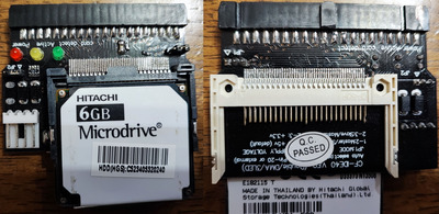
Previously I've tested those 16-bit VGA cards without I/O card installed. Just POST card and VGA card and then got the beeps. But when I tested the battery (it made no difference) I also happened to have multi I/O card installed. And not only that, it had CF-to-IDE adapter and Hitachi Microdrive installed.

I removed the POST card (and XT-CF I had for XTIDE Universal BIOS) so just 16-bit VGA card and multi I/O card with adapter and microdrive. This works. Next I removed the I/O-card and got those VGA error beeps again. Did some more testing. I/O-card alone is not enough, it MUST have the CF-to-IDE adapter with or without microdrive. I tried with two different hard disks installed and those did not work. So the CF-to-IDE adapter does something to fix things. But what could it be?

Edit: Here is a picture of the CF-to-IDE adapter I tested with:

CF_adapter.jpg
Filename
CF_adapter.jpg
File size
1.52 MiB
Views
1455 views
File license
Public domain
Last edited by aitotat on 2023-02-13, 18:15. Edited 1 time in total.

Reply 7 of 27, by Deunan

User metadata
Rank Oldbie
Rank
Oldbie
aitotat wrote on 2023-02-13, 18:00:

So the CF-to-IDE adapter does something to fix things. But what could it be?

This is just a guess, but perhaps a pull-up (or pull-down, or just more load on the lines) somehow helps to clean up one of the signals? Some cards might also inject wait states to have more time to properly decode the address (this is usually only required for I/O, not memory, but can be on both).

If you have 3k3 or 4k7 resistor you can connect one lead to +5V and the stick the other into one of the 16-bit ISA signals you suspect to be causing issues, see if that changes anything without the IDE card. If nothing changes, repeat but with connection to GND. Obviously it could be more than one signal or indeed the waitstates but at least it's simple enough to test.

Reply 8 of 27, by aitotat

User metadata
Rank Member
Rank
Member

I previously tested VGA cards on every 16-bit slot. And the motherboard was washed before I started doing repairs. I don't think it is a bad contact. I even resoldered the first 16-bit slot (the 16-bit part only) since most of the 16-bit ISA signals first go to that slot.

Reply 9 of 27, by aitotat

User metadata
Rank Member
Rank
Member

I checked all (used by the I/O card) ISA pin pull-up and pull-down resistances first without any card, then with I/O card and finally with I/O card + CF-adapter. ALE signal indeed seems to be the problem.

The working 8-bit VGA card doesn't have it connected but all the 16-bit cards do. What the CF-to-IDE adapter does it that is shorts ALE to ground. Resistance between ALE and ground is 15.7 Kohms without any card connected, 12 Kohms with just the I/O card and zero when the CF-to-IDE adapter is connected to it. ALE goes directly to one of the pins on HT18. There is no pull-up or pull-down resistor between and that is how it should be according to HT18 datasheet.

First I tried 1 Kohm resistor between ALE and GND. 16-bit VGA did not start. Next I tried 12 ohm resistor and now it did start! So shorting ALE to GND is the fix but why? I could easily fix this with very short wire below the board but is this really the fix? If the CF-to-IDE-adapter does it, then it should be safe? But I want to understand what is going on before doing this kind of "fix".

Reply 10 of 27, by mkarcher

User metadata
Rank l33t
Rank
l33t
aitotat wrote on 2023-02-21, 22:20:

If the CF-to-IDE-adapter does it, then it should be safe?

Well, for some strange definition of "safe", maybe. ALE is supposed to be output by the chipset, and IIRC the general rule is that ISA bus signals (like ALE) may be loaded with two TTL loads per ISA slot. A twelve ohm resistor to ground vastly exceeds that. Most logic chips can tolerate an output shorted to ground or 5V, at least for a short period. You shouldn't intentionally short logic signals for an extended period of time, though. If all your ISA cards are fine with ALE being grounded all the time, you can short ISA ALE to ground, but you should disconnect ISA ALE from the HT18 in this case.

I don't understand why pulling ALE low all the time works. It makes sense for 16-bit VGA cards to depend on ALE, as the high address bits A20-A23 (required for LFB access in the 1MB to 16MB "extended memory" range) only exist in an unlatched copy on the ISA bus. If a VGA cards want to keep these bits stable during the whole cycle, it needs to do latching of those bits itself. Address bits are supposed to be latched on the rising edge of ALE, and evaluated by cards on the subsequent falling edge. Your resistor likely suppresses all edges, which doesn't seem to make sense to help for an edge-triggered signal.

Reply 11 of 27, by Horun

User metadata
Rank l33t++
Rank
l33t++

Is there a logical reason the CF adapter constantly grounds the ALE line ? Would think that would violate protocols.... just wondering

Hate posting a reply and then have to edit it because it made no sense 😁 First computer was an IBM 3270 workstation with CGA monitor. Stuff: https://archive.org/details/@horun

Reply 12 of 27, by rasz_pl

User metadata
Rank l33t
Rank
l33t

ATA standard changes strike again?
ALE is used for address pipelining. Screwing with ALE would explain rare cases of Graphical glitches as mentioned here on 286 board IDE/CF adapter causing screen corruption/missing characters
>So instead of saying American Megatrends Inc, it'll look more like "Am ric n M atr nds I c" or something similar.
>If you run at 8Mhz, it POSTs every time, boots every time, no weird character corruption. https://imgur.com/a/YtJ4nzW
15JGo2D.jpeg

and here on "386SX 20MHz, some VLSI chipset" Re: SATA HARD Disk in 286/386 Mobo: Is it possible?
file.php?id=151649&mode=view

https://alexandrugroza.ro/microelectronics/sy … e-schematic.png shows one way for IDE controller to accommodate ATA1 IDE pin 28 change from BALE to CSEL | Cable select.

Compact Flash: https://resources.winsystems.com/datasheets/c … g-xxxm-i-ds.pdf:

-CSEL
(True IDE Mode)
This internally pulled up signal is used to configure this
device as a Master or a Slave when configured in the True
IDE Mode. When this pin is grounded, this device is
configured as a Master. When this pin is open, this device is
configured as a Slave.

This explains CF to IDE converter pulling this pin low to force Master. CF to IDE converter is made according to ATA1 standard and doesnt anticipate anyone routing it straight to ISA connector.

http://users.utcluj.ro/~baruch/sie/labor/ATA- … ATA-ATAPI-6.pdf
>When used as CSEL, this line is grounded at the host and a 10 kW pull-up is required at both devices
>Special cabling may be used to selectively ground CSEL. CSEL of Device 0 is connected to the CSEL
conductor in the cable, and is grounded, thus allowing the device to recognize itself as Device 0. CSEL of
Device 1 is not connected to the CSEL conductor, thus the device recognizes itself as Device 1.

https://hddguru.com/download/documentation/AT … ATA-ATAPI-1.pdf
>Prior to the introduction of this standard, this signal was defined as DALE
(Drive Address Latch Enable), and used for an address valid indication from
the host system. If used, the host address and chip selects, DAO through DA2,
CS1FX-, and CS3FX- were valid at the negation of this signal and remained
valid while DALE was negated, therefore, the drive did not need to latch these
signals with DALE.

Imo best course of action would be isolating pin 28 between CF_to_IDE converter and IDE controller. This of course doesnt explain why OPs computer works correctly only with this standard violating glitch. It would be prudent to use scope/logic analyzer/logic probe and see what chipset is outputting on ALE pin in the first place. Maybe its stuck high blocking VGA from working at all while stuck low merely disables early address decoding with the card waiting one more cycle before asserting -memcs16.

Open Source AT&T Globalyst/NCR/FIC 486-GAC-2 proprietary Cache Module reproduction

Reply 13 of 27, by Deunan

User metadata
Rank Oldbie
Rank
Oldbie

IIRC on some mobos the ALE signal is being driven during memory refresh cycles, and it shouldn't be. If that refresh cycle happens during read/write to VGA VRAM, it can screw up addressing and glitch the operation.

As to why it works with the signal grounded - actually quite a lot of VGAs can work in 8-bit slot and thus can ignore the ALE, or use it in weird ways (like a level signal instead of edge one). That's why I suggested masking the contact on the edge connector with a piece of tape. This sometimes works, but it depends on what the card does with the signal internally and if there are any pull-ups/downs on the PCB as well. It might become slower too, thinking it is inserted into 8-bit slot and just ignore all 16-bit transfers.

Point is, it cannot be easily fixed. Unless the mobo can properly refresh RAM (things like hidden refresh in BIOS can help, but then again mobos that offer that already do refresh properly anyway) the only other way is to find a VGA card that is both fast enough and does not use, or can be made not to use ALE signal at all.

Reply 14 of 27, by RayeR

User metadata
Rank Oldbie
Rank
Oldbie

Hm, an interesting bug. Did you checked the ALE pin (on chipset side) by multimeter diode test? You should see cca 0.6v drop when mulimeter plus connected to gnd and minus to ALE pin. Similar against to 5VCC. Just to check if this pin is not blew off inside chipset (that may happened if someone plugged something bad to ISA slot before as there's no any buffering)...

Gigabyte GA-P67-DS3-B3, Core i7-2600K @4,5GHz, 8GB DDR3, 128GB SSD, GTX970(GF7900GT), SB Audigy + YMF724F + DreamBlaster combo + LPC2ISA

Reply 15 of 27, by mkarcher

User metadata
Rank l33t
Rank
l33t
mkarcher wrote on 2023-02-21, 22:51:
aitotat wrote on 2023-02-21, 22:20:

If the CF-to-IDE-adapter does it, then it should be safe?

I don't understand why pulling ALE low all the time works.

Reading the other thread, it suddenly clicked for me. I used to think about the ALE signal as a signal that helps you deal with the unlatched address signals LA17-LA23. And according to the Intel ISA specification, only edge triggering makes sense in that case, because the falling edge of ALE indicates the point of time LA17-LA23 can be sampled to obtain a copy that is stable during a bus cycle. But you can use ALE a second way: If ALE is low, SA0-SA19 is stable, because SA0-SA19 are the outputs of those latches that are "enabled" by "ALE (address latch enable)", and "enable" in that case means "output follow the input", whereas "not enabled" means "output frozen". It thus makes sense for a VGA card to wait for ALE to drop to low before sampling SA0-SA19 and start executing a memory or I/O cycle. If ALE on your board is stuck high for some reason, the "ALE is low" condition might never happen, causing strange issues for a card waiting for "ALE low".

Reply 16 of 27, by mkarcher

User metadata
Rank l33t
Rank
l33t
Deunan wrote on 2023-02-22, 15:12:

IIRC on some mobos the ALE signal is being driven during memory refresh cycles, and it shouldn't be.

I'm surprised to hear about ALE being related to memory refresh, yet you likely are right that ALE is not supposed to be driven during refresh on any kind of DMA cycles, including XT-compatible memory refresh signalling. ALE is an output of the processor bus interface, and RAM refresh is not performed through that interface, so no ALE is expected during refresh.

Nevertheless, is it possible that you confuse ALE and AEN? Both of these signals belong to the more mysterious signals on the ISA bus. AEN is driven by the DMA controller to avoid false I/O port responses during DMA transfers. Cards are supposed to ignore IORD and IOWR while AEN indicates a DMA cycle, but some cards (e.g. the cheap POST cards) don't do so.

Deunan wrote on 2023-02-22, 15:12:

If that refresh cycle happens during read/write to VGA VRAM, it can screw up addressing and glitch the operation.

Well, that's supposed to be impossible to happen. Read/Write cycles to VGA VRAM only happen when the processor is owner of the ISA bus; RAM refresh cycles only happen when the refresh controller (in PC/XT computers: the DMA controller) is owner of the ISA bus. You can't have the processor and the refresh controller being owner of the ISA bus at the same time.

Reply 17 of 27, by Deunan

User metadata
Rank Oldbie
Rank
Oldbie
mkarcher wrote on 2023-02-22, 18:24:

RAM refresh cycles only happen when the refresh controller (in PC/XT computers: the DMA controller) is owner of the ISA bus. You can't have the processor and the refresh controller being owner of the ISA bus at the same time.

True, but on pretty much any AT+ mobo with chipset that emulates the DMAC, INTC, etc, the memory addressing and (de)multiplexing is being done in the chipset. So it can easily refresh the RAM banks while CPU is talking to the ISA, these are now completly separate busses. Might even be more than those two, with separate "private" data/address bus that goes to an integrated '206 type chip, separate from actual ISA cards.

Perhaps you are right and I am confusing two different issues, my memory is more than a little bit hazy on the actual details. With the refresh the problem was signals were appearing on ISA at times they should not have (or the opposite?). Could be that was a spurious or missing AEN. Then with ALE there was something about the timing of it being wrong - but perhaps it's just random and not refresh related? I tried to investigate it long time ago but back then I didn't have the tools and skills I have now so I didn't get very far, and now... frankly I'm too busy and too lazy to dive into that.

Reply 18 of 27, by aitotat

User metadata
Rank Member
Rank
Member
RayeR wrote on 2023-02-22, 15:34:

Did you checked the ALE pin (on chipset side) by multimeter diode test?

Multimeter+ to GND and multimeter- to ALE shows 0.7V. Multimeter+ to +5V and multimeter- to ALE shows 1.1V. So these should be good?

I did more testing as well. I have one of those cheap portable oscilloscopes and I'm learning to use it. There is definetly activity on ALE pin but I'm not sure it is what it should be. Sometimes there is a good looking signal that stays high a while and then drops. But then there are also spikes that immediately drops.

I tried to tape ALE pin from two of the 16-bit ISA cards. They did not work so they definetly need the ALE.

Reply 19 of 27, by RayeR

User metadata
Rank Oldbie
Rank
Oldbie

When measured TTL output against VCC, it should show 0,7V with multimeter minus at VCC or 1,2V with multimeter plus at VCC so it seems to be OK. Also you mention the signal is generated from this pin, so output is probably OK and problem is somewhere else, no idea...

Gigabyte GA-P67-DS3-B3, Core i7-2600K @4,5GHz, 8GB DDR3, 128GB SSD, GTX970(GF7900GT), SB Audigy + YMF724F + DreamBlaster combo + LPC2ISA