First post, by treeman
Rank
Oldbie
I have a 486 motherboard which I suspect the clock generator is not working. To troubleshoot it I want to learn more exactly how this circuit works.
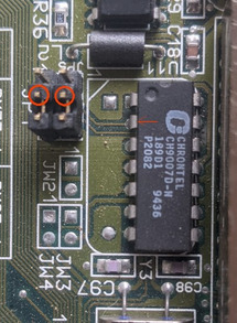
On my pcb I have a standard 14.318mhz crystal next to a chrontel clock generator. Using a multimeter in hz mode I got nothing direct from the crystal, got 6mhz for a second and seen it once or twice during many tests. So I had a spare crystal swapped it and still the same.
The crystal's pins are directly connected to 2 pins on the clock gen going through some smd caps.
This is where I am looking at how the logic in this circuit behaves. Does the clockgen chip send the power to the crystal then receive the pulses back, then converts them to a square wave and different speed. frequencies?
Last edited by treeman on 2023-03-10, 21:20. Edited 1 time in total.