VOGONS


First post, by jklaiho

User metadata
Rank Newbie
Rank
Newbie

So, I've got my new old stock AT case and as I was preparing to connect all the 2- and 3-pin cables to the motherboard, I realized that none of them were actually labeled (and I don't have a manual). The mobo (an Intel Advanced/ZP "Zappa") has labels next to the pins, but their arrangement and the way pins are missing are just bewildering.

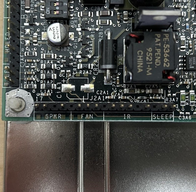
The mobo came with the CPU installed, and I just removed the fan for the pictures. Its connector (not pictured) was on the rightmost two pins on the FAN header. The speaker cable (also not pictured, it's not integrated into the case) is obvious, with just two possible ways of attaching it. The case doesn't have a keylock, so that'll probably be left empty.

But other than that, I don't know what goes where, and I wouldn't want to blindly try all possible permutations, just in case this could end up damaging something.

  • Is there supposed to be some kind of standard coloring here that I couldn't find? If not, do I just have to guess what goes where?
  • Do I orient all the cables so that the arrow on the connector is nearest to the no. 1 pin on the header?
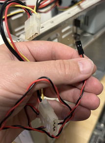
  • What on earth is that one 2-pin black/red cable that comes from the PSU? I couldn't find any references to it.

I used to build a bunch of PCs back in the day, but I guess they were all in the ATX era, where this got somewhat simpler.
Attachments

  • IMG_5500.jpeg
    Filename
    IMG_5500.jpeg
    File size
    290.48 KiB
    Views
    385 views
    File comment
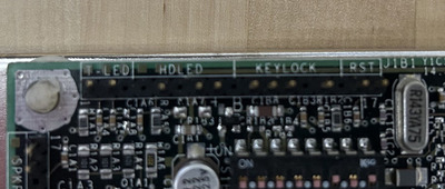
    T-LED/HDLED/KEYLOCK/RST
    File license
    Public domain
  • IMG_5504.jpeg
    Filename
    IMG_5504.jpeg
    File size
    200.94 KiB
    Views
    385 views
    File comment
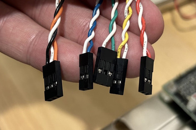
    The case connectors
    File license
    Public domain
  • IMG_5503.jpeg
    Filename
    IMG_5503.jpeg
    File size
    136 KiB
    Views
    385 views
    File comment
    2-pin from the PSU
    File license
    Public domain
  • IMG_5499.jpeg
    Filename
    IMG_5499.jpeg
    File size
    311.83 KiB
    Views
    385 views
    File comment
    SPKR/FAN/IR/SLEEP
    File license
    Public domain

Reply 1 of 5, by Warlord

User metadata
Rank l33t
Rank
l33t

orientation only matters for Power LED and Reset LED. If you connect those backward it wont kill the led or the board the led just wont work. turbo switch and reset switch the orientation does not matter. You should be able to figure out which wire comes from which thing by taking off the front cover bezel, thats if you can visually see them.

Those are AT standard wires though atleast for the power switch. AT Standard the power switch was directly wired to the PSU and the switch was live 110 or 220 V on the front of the case that you turned on and off like how a light bulb is. So you shouldt have one of those. You should have a reset wire, turbo switch wire, speaker wire, a power led wire, a turbo LED wire and maybe a power switch led wire.

The 3rd picture of you holding the wire with the black and red connected to one of the Molex leads comming from the PSU is not a motherboard connector. That is likely a lead to go to a turbo LED display, the one that shows the numbers do not connect that one to the motherboard unless you want to fry somthing. Turbo LED display is not the same as turbo LED.

Reply 2 of 5, by TheMobRules

User metadata
Rank Oldbie
Rank
Oldbie
jklaiho wrote on 2023-07-03, 14:49:

So, I've got What on earth is that one 2-pin black/red cable that comes from the PSU? I couldn't find any references to it.

Careful with that one. It’s a 5V connector that does NOT connect to the motherboard at all, it is used to power the MHz display on the front of the case. You need to plug it in the correct orientation (red = +5V, black = ground) or you’ll blow the display.

As for the rest of the connectors, there is no “official” color coding, but in your case it seems that Green = Power LED, Yellow = Turbo LED, Blue = Reset switch, Red = HDD LED, and the 3-pin one is the Turbo switch.

Intel always had a somewhat odd way to place the front panel connectors, so from the picture you posted the motherboard headers are connected as follows (from left to right):

  • T. LED = Turbo LED, this one is obvious, if it doesn't work just reverse it
  • HDLED = HDD LED, use the two rightmost pins, the other one remains unconnected
  • KEYLOCK = ignore the first two if you don't have a keylock in your case, then you have pin-empty space-pin that is for the Power LED
  • RST = Reset switch, this one is also obvious, it has just 2 pins

I don't see a header for the Turbo switch, if the motherboard doesn't have one you can just leave it unconnected.

Last edited by TheMobRules on 2023-07-03, 16:02. Edited 1 time in total.