VOGONS


First post, by TheMobRules

User metadata
Rank Oldbie
Rank
Oldbie

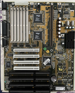
I have this early Pentium II motherboard, based on the 440FX chipset. Model name is "R653", apparently manufactured by "m-tech":

R653_Board.JPEG
Filename
R653_Board.JPEG
File size
460.84 KiB
Views
490 views
File comment
R653 Pentium II motherboard
File license
Public domain

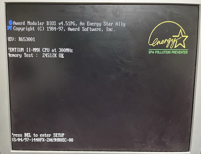
The problem is it appears to be completely dead. And when I say "completely" I really mean it. When I hook up a power supply (tried several known working ones), pressing the power button results in absolutely nothing. The power supply doesn't even start (or even try to start and immediately shut off, like when there is a short). So no indicator lights, fans or anything else turn on either.

Therefore, I turned my attention to the power-on circuit. On more modern boards this is handled by the southbridge (usually a BGA chip) so if that was the case it would probably be game over. But since this is an early ATX board and there is no BGA filth there may yet be a chance.

Now, it seems the entire power-on/soft-off feature on this board is handled by the ITE IT8680F I/O chip (datasheet attached):

R653_IOChip.JPEG
Filename
R653_IOChip.JPEG
File size
62.75 KiB
Views
490 views
File comment
ITE IT8680F
File license
Public domain

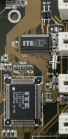
By following the traces on the motherboard, the IT8680F seems to be the only chip connected to the +5VSB line of the power supply. These are my findings:

  • When I flip the switch on the back of the PSU, I get 5V standby voltage on pin 78 (VCCH) as expected
  • On pin 75 (VBAT) I get the 3V from the CMOS coin cell battery
  • Pin 74 (PWRON#) is connected to the PS-ON line of the power supply, again as expected
  • Pin 69 (SWITCH#) is connected via a 33 Ohm resistor to one of the pins of the power button header (the other pin is GND) and it is also pulled high to +5VSB with a 4.7kOhm resistor
  • The 32.7kHz RTC crystal measures OK, as well as all the passives around the area
  • None of the tantalums seem shorted, and there are no shorts on the power supply lines

If I'm not mistaken this points to the ITE chip being bad, otherwise pressing the power button should result in the IT8680F grounding the PWRON# line and causing the PSU to start right?

A common failure scenario on older ATX power supplies was the +5VSB line going rogue and killing whatever was connected to it, so hopefully that was the case here and the ITE chip was the only victim. All the components on the board look pristine, no burn marks or anything weird.

I may be able to get a new ITE chip from UTSource for about $3, but before I start desoldering stuff I wanted to check if anyone has suggestions of something I may be missing here.

Thanks in advance!

Attachments

  • Filename
    ITE8680F.PDF
    File size
    608.22 KiB
    Downloads
    34 downloads
    File comment
    ITE IT8680F datasheet
    File license
    Fair use/fair dealing exception

Reply 1 of 5, by Horun

User metadata
Rank l33t++
Rank
l33t++

Before doing anything to the board (assuming the current PSU is 100% good) I would check the board for direct shorts first w/o cpu, ram, adapters and no psu: at the psu connector using ohms (not continuity) on the digi meter
I would then force PSU to start by shorting the green lead (Power on) to any black Ground lead at the PSU connector and see what happens, many times it is works ok to force PSU on depending on the PSU.
added/edit: I did not see the POWER-GOOD in datasheet, unless I missed it. if it was then the PSU may not get a "power good' return signal so will not start if that IC is blown. Usually the power good comes from a diff spot but not always....
Besides a vid card and monitor make sure you have a POST card installed before forcing the PSU so you can watch to see if any activity. If not could be in the power good circuit.

Hate posting a reply and then have to edit it because it made no sense 😁 First computer was an IBM 3270 workstation with CGA monitor. Stuff: https://archive.org/details/@horun

Reply 3 of 5, by TheMobRules

User metadata
Rank Oldbie
Rank
Oldbie
Horun wrote on 2023-08-28, 01:14:
Before doing anything to the board (assuming the current PSU is 100% good) I would check the board for direct shorts first w/o […]
Show full quote

Before doing anything to the board (assuming the current PSU is 100% good) I would check the board for direct shorts first w/o cpu, ram, adapters and no psu: at the psu connector using ohms (not continuity) on the digi meter
I would then force PSU to start by shorting the green lead (Power on) to any black Ground lead at the PSU connector and see what happens, many times it is works ok to force PSU on depending on the PSU.
added/edit: I did not see the POWER-GOOD in datasheet, unless I missed it. if it was then the PSU may not get a "power good' return signal so will not start if that IC is blown. Usually the power good comes from a diff spot but not always....
Besides a vid card and monitor make sure you have a POST card installed before forcing the PSU so you can watch to see if any activity. If not could be in the power good circuit.

Yes, force-starting the PSU is the most logical thing to do in this case, how didn't I think about doing that? 🤦 Anyway, thanks a lot for the suggestion because I grounded the PS-ON signal on the power connector and guess what:

R653_POST.JPEG
Filename
R653_POST.JPEG
File size
258.11 KiB
Views
423 views
File comment
POST screen
File license
Public domain

Yup, got a POST! And everything seems to be working just fine, board is MemTesting now. Most surprisingly the devices controlled by the ITE chip all appear to work without problems (floppy drive, keyboard, serial/parallel ports). This is a bit puzzling, as it would mean that only the power-on capability is broken on that chip? That doesn't seem to be a likely scenario, although it is not impossible I guess.

Regarding the PG signal, that is not handled by the ITE chip but by some components near the front panel connectors. In any case, if PG was the problem the PSU would at least start but the CPU would not get out of reset. This seems more like a case of the ITE chip being unable to detect that the power switch was pressed and so it doesn't tell the PSU to start.

dm- wrote on 2023-08-28, 03:54:

1. check for 3.3v on power button jumpers

3.3V? I thought the power-on circuit only uses the 5V standby, the other lines are not turned on at this point.

dm- wrote on 2023-08-28, 03:54:

2. check for 32khz oscillator near by ITE chip. oscillator must work properly for power on.

Oscillator seems fine (32.76 kHz) though I have only tested it with a frequency meter as I don't have a scope at hand.

Very strange, I'll keep investigating...

Reply 5 of 5, by TheMobRules

User metadata
Rank Oldbie
Rank
Oldbie
dm- wrote on 2023-08-28, 04:07:

3.3v on the power button is from transistor and 5v PSU standby.
dead transistor, no power on button, no start. something like this

check the power button circuit

Gotcha 👍 , I see a 3904 NPN near the headers that may be part of the power-on circuit. I'll check the voltage on the header pin and will try to trace the circuit.