VOGONS


First post, by stlouis1

User metadata
Rank Newbie
Rank
Newbie

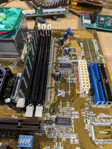
I have a pair of A7V266-E boards here that I acquired recently, both 1.07 revisions. Both had bad caps and I found a thread here on that topic which was useful in finding suitable replacement caps for the four 6.3v 3300uf nichicons that popped. I've only replaced those 4 capacitors on each board

Now the first one I never even tried to power on before replacing capacitors so I don't know if it's new behavior, but when I plug it in, I can see the power LED on the board light up, but if I jump the power button connectors, it does nothing at all. No fan spin, nothing.

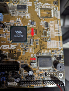
The second board however, does power on, but just keeps giving me a continuous beep. A post card gives me a C2 code, all of which tells me it's a memory issue. All I have at hand is later PC3200 DDR and a single stick of PC2700. I've tried all of the DDR I have and the issue remains the same. I wonder if these boards were picky with ram? or maybe the board has another issue?

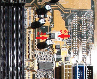
edit/// actually, I'm looking over the rest of the board, and this capacitor close to the memory seems a bit sideways. I half wonder if it popped from the bottom or if it was just soldered in a bit crooked during manufacturing. I wonder if I should replace it... I do have some rubicon yxs caps in stock that match the voltage and capacitance rating but not sure off the top if they'd be quite the right replacement

Attachments

Reply 2 of 7, by stlouis1

User metadata
Rank Newbie
Rank
Newbie

Yes I do have 2.62v reading there

actually, might be mistaken on the post codes. the one post card I have shows 00 c2 on 2 different displays. I guess c2 is the previous step and 00 is where it stopped? I tried another post card and it passes C2 and stops at 00 .... not sure what that means but maybe it's not ram?

Reply 4 of 7, by stlouis1

User metadata
Rank Newbie
Rank
Newbie

I had that thought earlier myself and interestingly, while both of these are the same revision of the board, the other has a soldered bios.... I really need a programmer for those because I do have a ton of them in a container that I could program and swap on this board

Reply 5 of 7, by stlouis1

User metadata
Rank Newbie
Rank
Newbie

just running my meter across different places on both of these boards to compare. Still can't get the one that turns on to post, but it powers on, unlike the other. Couple points of interest though

On the board that powers, I'm not measuring any voltage to this crystal pointed out in the picture, and I only measure about 0.75v to this pin on this asus IC

On the board that doesn't power on, I'm measuring 1.5v to the crystal, and 3v to that same pin on the IC

This is with just a new CR2032 battery on the board

Not sure what to make of this yet but....

Attachments

  • Untitled.jpg
    Filename
    Untitled.jpg
    File size
    386.09 KiB
    Views
    355 views
    File license
    Public domain

Reply 6 of 7, by Karbist

User metadata
Rank Member
Rank
Member

when board is connected to psu and standby 3.3v rail is present, you should have 1.4v on one leg of crystal and 0.7v on the other leg.
also disconnect the board from psu and put your multi meter in diode mode, with black probe on the ground you shouldn't have any voltage drop on the crystal legs and with red probe on the ground you should have around 0.5v voltage drop on each leg.

The pin on the IC is 3v coming from battery + standby rail.
this is the board view for this model, you need to install boardviewer to open it.
https://pixeldrain.com/u/b1A6rL6C

Reply 7 of 7, by stlouis1

User metadata
Rank Newbie
Rank
Newbie

not sure if i'm doing something wrong with diode mode on my meter or if it's just really basic... it is a pretty old and basic meter though. but with diode mode and no power connected i just get inconsistent beeps out of the meter

that said, measuring voltage on the crystal lets while the psu is connected i get .7v on one leg and .8v on the other. definitely nowhere near 1.4v...