VOGONS


First post, by DamienC

User metadata
Rank Newbie
Rank
Newbie

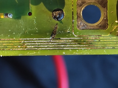
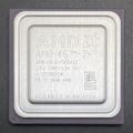
I don't remember how I acquired this board, but it was working when I got it despite having some pretty severe corrosion from an exploded barrel battery. About 10 or 15 years ago I smoked an AMD 386DX-40 in it by being careless and putting it in the wrong way. The board hasn't worked since, but I have been attempting to clear out some older PC components and I'd like to tinker with this and see if I can get it working because it was a very nice 386DX board and I have a few TI 486DLC chips lying around.

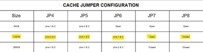
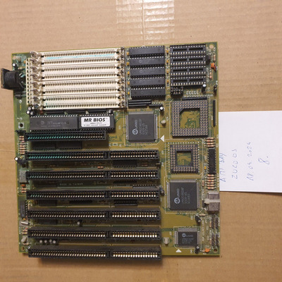
The board has 6 16-bit ISA slots, 1 8-bit slot, a UMC 82C48X chipset, CPU and FPU sockets, 8 30-pin SIMM slots, 2 Cache banks (IIRC this had 128k cache installed), a JETKey 3.0 keyboard BIOS, and most interestingly, a Mr. BIOS chip. I've never used a better BIOS. It had so many options.

I have no clue who made this board, and the board itself is very spartan as far as markings go. There is a serial number and manufacture date on the side of one of the ISA slots, and has "Made in Taiwan" etched on the board. No other markings appear anywhere, and there isn't even a legend for the few jumpers it has.

Here are some pics:

386dx-002.png
386dx-003.png
386dx-004.png
386dx-005.png
386dx-001.png

And I used my EPROM programmer to dump the Mr. BIOS. File is attached.

Anyone have an idea of the make/model, or even just what the jumpers do?

Attachments

  • Filename
    m351 mr bios.zip
    File size
    43.69 KiB
    Downloads
    58 downloads
    File license
    Public domain

Reply 1 of 10, by computerguy08

User metadata
Rank Member
Rank
Member

This was the luckiest find I had in a while. The schema is absolutely out of proportions (way larger than your board), but the jumpers actually match 100% (th99 was known to have such bugs though, so it's okay)

http://www.win3x.org/uh19/motherboard/show/5409

The photo you took is okay and it is useful for the page in uh19, but if you could take a better photo on a straight surface (like a tabletop), I would really appreciate it. I'm especially requesting this because it's a very poorly documented board.

Reply 2 of 10, by DamienC

User metadata
Rank Newbie
Rank
Newbie

No problem. This is the best I could do while wrangling my kids, I might be able to take a better one later when they're in bed.

IMG-20201211-174159949-HDR.jpg

Glad I could contribute, I knew this board was unique for the BIOS alone so I at least wanted to get that out there even if I can't get it working again.

Reply 4 of 10, by dheadz

User metadata
Rank Newbie
Rank
Newbie

DamienC:
Have You progressed forward to revive this board?

I own a board like this and thanks to computerguy08, finally I was able to identify it. Mine works flawlessly 😀
Luckily just a few jumpers was needed to take care with.

According to Your pictures (+ the manual @computerguy08's page), the jumpers next to the left side of the cache ICs are in incorrect position.

Tested 128k & 256k settings as well.

The other thing - I observed Your board is missing 2 resistors: R32 (470 Ohm), R36 (1k Ohm). Interesting there are 2 picture on the manual's page, one yellow PCB + one green PCB. The resistors missing of the former, but exits on the green one..

If You need me to check anything else on the board or measure components etc., just shout me.

Attachments

Reply 5 of 10, by dj_pirtu

User metadata
Rank Member
Rank
Member

Got this board too with bad corrosion on battery corner, SIMM- and ISA-slots are affected too. Reason I wanted this mobo is the chipset, it takes high FSB clocks and is great for overclocking. Good base for a 386-system which can run FastDoom.

Now it's bathing in vinegar and later I'll wash the board and check the traces, hope I'll get it working...

Attachments

Reply 6 of 10, by dj_pirtu

User metadata
Rank Member
Rank
Member

No way I can fix those lines, just too small for my eyes and equipment... 🙁

Attachments

Reply 7 of 10, by Jo22

User metadata
Rank l33t++
Rank
l33t++
dj_pirtu wrote on 2024-05-15, 07:17:

No way I can fix those lines, just too small for my eyes and equipment... 🙁

It looks worse than it is, maybe.
The first line can be fixed by a fine resistor leg.
The other two with a fine solder blob. Desoldering braid can help if you do a mistake.

Any fix is better than giving up on the board. 😀

Edit: The second picture doesn't look so bad.
The first line needs a fix, the others are almost fine to me.

Applying solder flux can help to make the connections less brittle.

Personally, I do use liquid rosin here (sold as soldering honey).

Last edited by Jo22 on 2024-05-15, 07:32. Edited 1 time in total.

"Time, it seems, doesn't flow. For some it's fast, for some it's slow.
In what to one race is no time at all, another race can rise and fall..." - The Minstrel

//My video channel//

Reply 8 of 10, by analog_programmer

User metadata
Rank Oldbie
Rank
Oldbie
dj_pirtu wrote on 2024-05-15, 07:17:

No way I can fix those lines, just too small for my eyes and equipment... 🙁

In this particular case, If you can't solder some very thin wires to restore the broken traces, it is useless to try to tin the traces inflicting more damage to the motherboard. Just hand the board to someone with proper soldering equipment.

from СМ630 to Ryzen gen. 3
engineer's five pennies: this world goes south since everything's run by financiers and economists
this isn't voice chat, yet some people, overusing online communications, "talk" and "hear voices"

Reply 9 of 10, by douglar

User metadata
Rank Oldbie
Rank
Oldbie

I was a little daunted by trace repair at first, but with a $30 soldering pen, $10 magnifying stand, fine tweezers, and plenty of patience, repairing 2 or 3 traces over a short distance isn't so bad. Seems like magic at first, but everything ends up going where you want with a little flux and a little heat in the right spot. Although it's always better to practice on an old modem or something first if you can find the time.

I sacrificed a the motor from a broken floppy drive a couple years back. I got a lifetime supply of trace repair wire out if it.