i want connect a floppy drive 5" to my pc xt, i have all schematics, but i don't know how solder can you help me?please....what mean the column ov???
beside the signals?
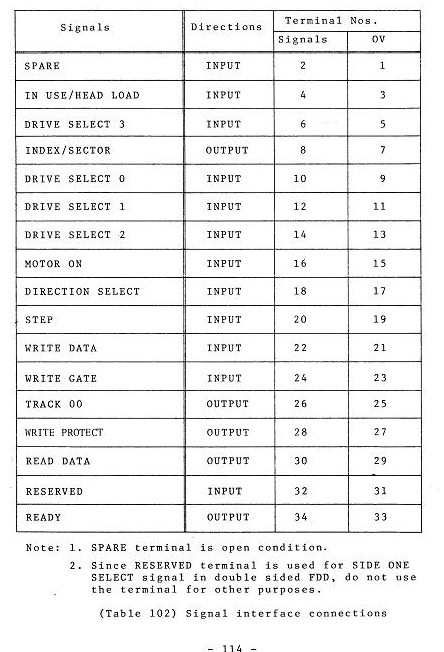
The OV prolly just is the corresponding ground pin ... seems useless, it is ... but that's how the 34 pin shuggart floppy interface is defined.
Additional possibly useless info: I'm not exactly familiar with the Schneider Euro PC, but I have a Schneider CPC (which is a unique 8bit design) ... that one can use virtually any PC floppy drive as long as you build a 1:1 cable (one side has the normal PC type connector, the other a centronics styled oned). Maybe it's the same on the Euro PC
thank you very much to reply.. the connector of the external drive of euro pc is db25, like parallel port, can you help to built cable ?you need other informations???
What TEAC drive do you have?
They made a huge load of different ones, some allowing you to set options for the floppy drive, that might be required
This is most likely how such an adapter would be wired up (no guarantees tho):
1DB25 (male) from EuroPC  Floppy connector
21. /INDEX	              8
32. NC	                  -
43. /DRIVE SELECT	       12
54. NC			            -
65. /MOTOR ON		        16
76. /DIRECTION	          18
87. /STEP		            20
98. /WRITE DATA		      22
109. /WRITE GATE		      24
1110. /TRACK 0		        26
1211. /WRITE PROTECT	     28
1312. /READ DATA		      30
1413. /SIDE 1 SELECT	     32
1514. +5 VOLT		         -
1615. +5 VOLT		         -
1716. +5 VOLT		         -
1817. +5 VOLT		         -
1918. POWER ON		        -
2019. NC			           -
2120. GND			 \
2221. GND			  \
2322. GND			   \
2423. GND			    |- Any odd pin
2524. GND			   /
2625. GND			  /
2726. GND			 /
You'll need an external +5/+12 volt power supply and make sure the floppy is jumpered as single (or double?) density.
I'd go as far and build you such an adapter, but considering there's no way I can make sure it's wired up correctly, I'd prefer not to, considering you might end up with a useless cable. Don't you have someone physically available to you who knows how to solder?
I've done that in the past for a very old 8086 laptop with broken floppy. It had a strange 26pin floppy. I'd managed to make a cable for a standard 34 pin floppy, but it couldn't fit in the laptop, as it's originall floppy was of very small height. It had an external floppy port, but I doubt if the wiring would be the same as the Schneider. I'd try Shock__'s wiring. And if you don't feel like soldering, just find an old printer cable with db25 on one side, cut it, and then do the same with a regular floppy cable, and you should be able to join the cables easier.
On the standard drive, the odd numbers(1,3,5,...33) are ground cables. So if you try the that wiring that is mentioned above, you should connect them to the last (20-25) pins of the schneider. But if I remember well, the external floppies connected to the parallel port or a special port for that purpose, had 5v on the last pins of the db25 port.. I suppose that the schneider is different, but just in case, I would test the last pins using a multimeter.
i power on my drive of 5 1/4" with external supply, even i will connect the dispair number(1,3,7,9,11etc) all to ...?can you make me a graphic of thath excuse me but i'm very poor in electronics and english!!!