VOGONS


First post, by Nvm1

User metadata
Rank Member
Rank
Member

I am restoring an old Thinkpad 300 and so far I managed to fix everything I encountered.
However now I the thing starts again the screen is having issues. At a could start it looks quite ok-ish like this:
20160415_144857_zps0wioxnom.jpg

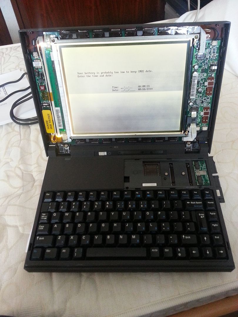
Some of the horizontal lines flicker a bit but it's readable etc. After a minute of 5 the screen starts losing its sharpness and after 10 minutes it looks like this:
20160415_145441_zpsdqmcey7l.jpg

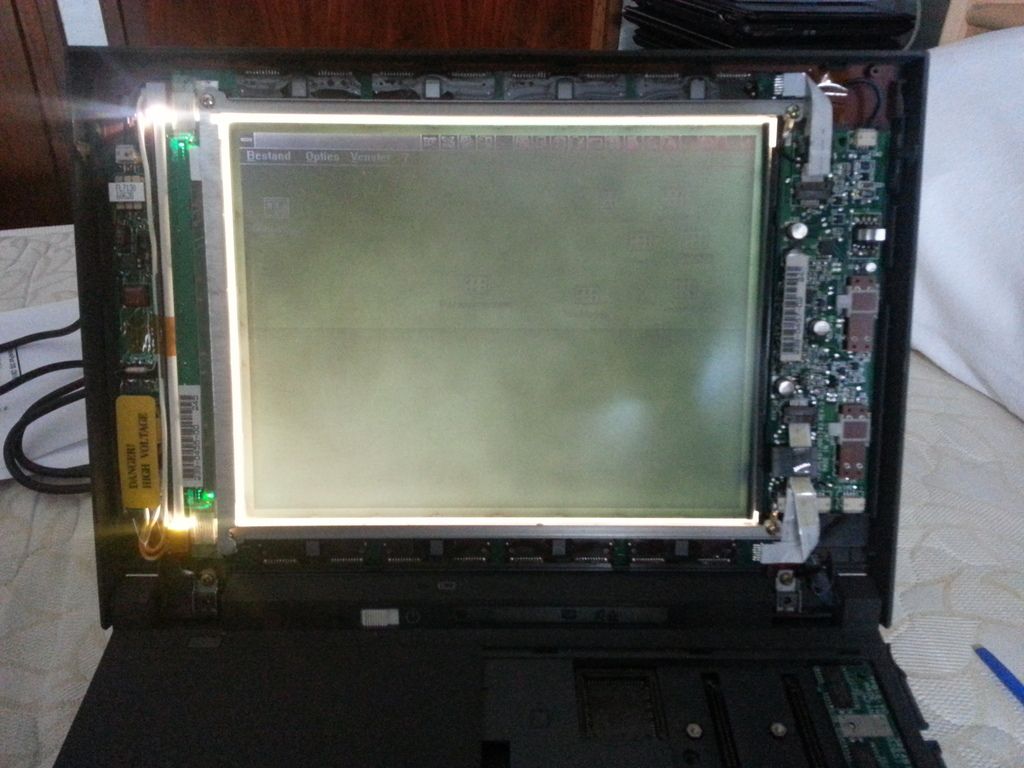
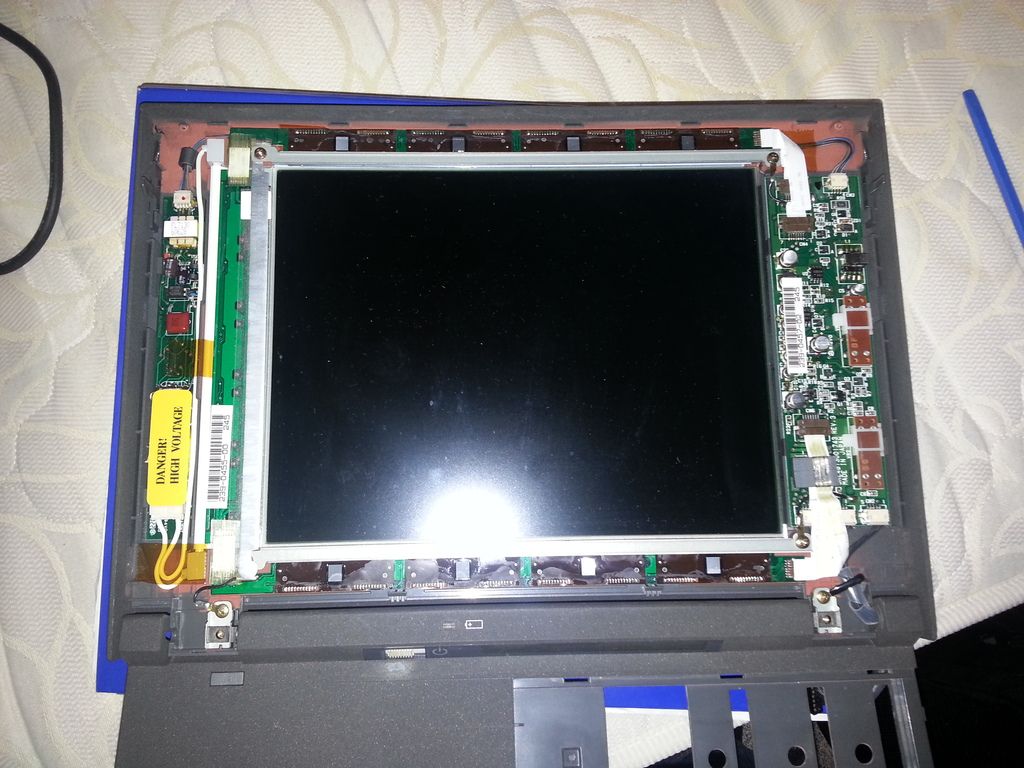
This has to be caused by something so I first thought the inverter was a goner and after getting warm it became dim but I was wrong. The backlight keeps working like a charm even after half an hour. (this screen is a separate lcd screen and backlight) So something controlling the contrast must be the issue. After disassembling the display you can see the control board on the right.
20160415_142144_zpseur7oipq.jpg

I checked the board and it seems have some leaking alu caps on it like the one in the middle of this board.
20160415_142214_zpsjohwwylu.jpg

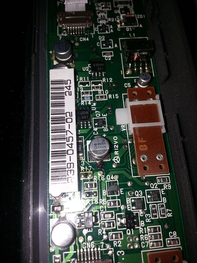
Except one all of them have black sticky goo coming out of them 😠
Now my question is, can these caps be the reason that the contrast disappears? And where can you get them and how can you see what capacity etc they have?
I hope some of you can help me with this. I will try to get a more detailed picture of the caps. I already cleaned the black goo but nothing more changed.

Reply 1 of 4, by h-a-l-9000

User metadata
Rank DOSBox Author
Rank
DOSBox Author

- the caps may be responsible for that, and additionally the liquid may corrode traces. One corroded trace can be seen below C4. After removing the caps there may be more damaged traces visible.
- to remove the old caps, if you don't have proper tools it's better to carefully cut off the caps in parts, then unsolder their pins. This way you don't risk pulling the pads from the pcb.
- check if the corroded traces are open, if yes solder a bridge.
- the values are printed on the caps - i.e. 1/50 is 1µF/50V, 22/35 is 22µF/35V.

I'd worry more about 'Some of the horizontal lines flicker a bit', but there's a chance this is also caused by caps...

1+1=10

Reply 2 of 4, by Nvm1

User metadata
Rank Member
Rank
Member
h-a-l-9000 wrote:
- the caps may be responsible for that, and additionally the liquid may corrode traces. One corroded trace can be seen below C4. […]
Show full quote

- the caps may be responsible for that, and additionally the liquid may corrode traces. One corroded trace can be seen below C4. After removing the caps there may be more damaged traces visible.
- to remove the old caps, if you don't have proper tools it's better to carefully cut off the caps in parts, then unsolder their pins. This way you don't risk pulling the pads from the pcb.
- check if the corroded traces are open, if yes solder a bridge.
- the values are printed on the caps - i.e. 1/50 is 1µF/50V, 22/35 is 22µF/35V.

I'd worry more about 'Some of the horizontal lines flicker a bit', but there's a chance this is also caused by caps...

Gonna try and get new caps then. I just need to know what caps I need since they have different ESR values if I look at the site from Mouser. Any idea how I can pinpoint the correct ones?

Reply 3 of 4, by h-a-l-9000

User metadata
Rank DOSBox Author
Rank
DOSBox Author

As this is not a high-current application I wouldn't bother with lowest possible ESR - the replacement should be 105°C rated for a long life and match in size.
I.e. this one should be a candidate: 647-UCL1V220MCL1GS

Or you wait for advice from the people here who know each capacitor personally 😉.

1+1=10