First post, by Miphee

Rank
Oldbie
- Rank
- Oldbie
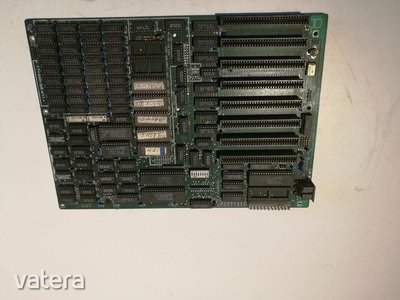
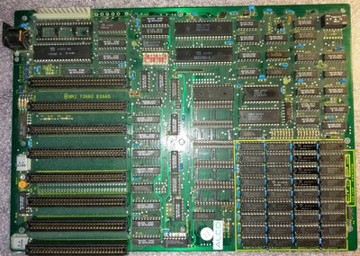
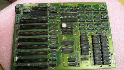
Any info would be appreciated. What is the pinout of this power connector? Thanks in advance.
Sorry for the shitty images.
Any info would be appreciated. What is the pinout of this power connector? Thanks in advance.
Sorry for the shitty images.
Use a multimeter and see how its connected to the ISA power lines.
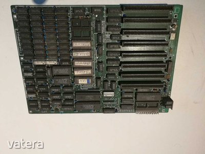
Looks like standart AT-power connector. Nothing special.
wrote:Looks like standart AT-power connector. Nothing special.
12 Pins - indeed you are right 😀
This is normal XT/AT power connector. Nothing fancy here.
New items (October/November 2022) -> My Items for Sale

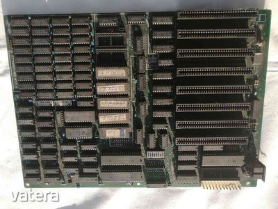
Pretty standard XT class alright. Clean it up, add a vga card, connect a monitor up, XT compatible kb if you have one, hook up a generic multi i/o card with 1.44meg drive attached and a 720k fdd boot disk, hook a known good AT PSU up turn it on and see what happens. looks like hit has 4 Basic options roms on it which is handy.
There's a glitch in the matrix.
A founding member of the 286 appreciation society.
Apparently 32-bit is dead and nobody likes P4s.
Of course, as always, I'm open to correction...😉
Thanks for the answers and the manual!
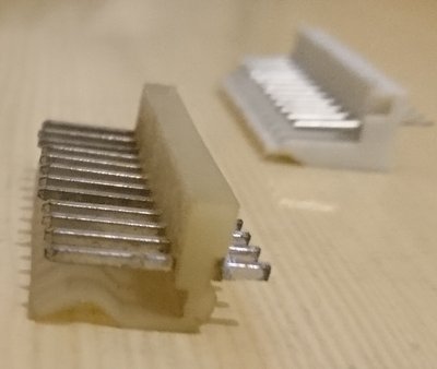
I'm confused because it doesn't look like a standard PSU connector that I know. The shape of the pins are also incompatible: one is flat-rectangular and the other is a square. It will 100% not attach to this board even though the pins are there.
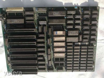
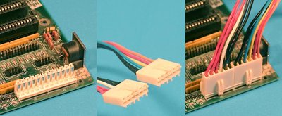
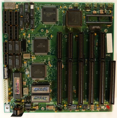
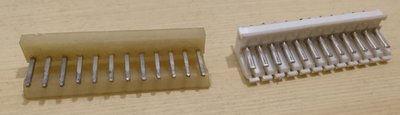
Attached a better quality example image of someone's board.
I'd rather find a PSU that fits this connector. XT boards are very scarce here, even generic clones.
Besides it's the period correct thing to do if I want to build an IBM XT clone but I need info.
Can't find anything about this connector type. Nothing on pinouts.ru either.
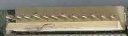
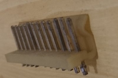
Think I see what you might mean - apart from the square pin profile, does the moulded part of the male P8P9 connector on the board have a full length securing lip instead of individual locating holes for each pin? Side view something like this:
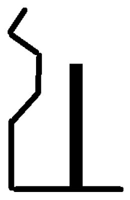
If so, not seen one like that before on a PC board, but possibly on TV / VCR internals.
Also, not every version of this board seems to be made like this
https://web.archive.org/web/20030222142114/ht … o/mct_turbo.htm
It's full lip secured. If the pinouts are identical to the standard P8P9 connector then I can just solder in a standard socket I have lying around.
But that's only as a last resort.
It seems that it was fairly common in XTs and early 286 boards.
Edit: awesome manual anyway, thanks!
Found one in my desoldered pile. Connector dimensions and spacings are identical.
A standard PSU's connector (P8P9) went in after using considerable force like Jesolo suggested it. If the pinouts are OK then it's acceptable.
I'm still curious about this connector and the correct PSU that fits. Any ideas?
Early OEM cases used this type of connector with their PSU's but, the pinout is identical to the standard P8 & P9 type connector.
I've come across the same problem with my XT motherboards.
However, if you are in doubt, then test the voltage output with a multimeter on the relevant pins. You'll see it matches the standard P8 & P9 pinouts 😀
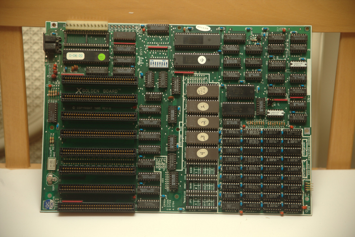
This looks like a copy of a copy to me. DTK Turbo 640, an extremely common board, has an identical layout.
Settings and stuff can be found here: http://www.uncreativelabs.de/th99/m/C-D/30501.htm
Manual can be found here: http://www.minuszerodegrees.net/manuals/Turbo … ion%20Guide.pdf
Looks like the DRAM type jumpers are hardwired instead of being populated here, so you're stuck using one memory configuration. Not much of a problem, honestly, since you've already got it fully populated anyways.
Would love to see a dump of what's on those expansion ROMs, though, both of mine just had the one 2764 EPROM, never seen one with more than one or two of it's ROM sockets full!
Those are standard XT/AT power connectors. This is a cheap Taiwanese board, and it was meant to go with it's cheap Taiwanese power supply. The supply is 100% identical to an XT's supply, maybe a bit beefier and with a slightly different connector on the end, but it's really nothing special. The pins of the PSU go really easily onto my IBM AT board and just fine onto the DTK board, but plugging the AT's supply into the DTK, even though the machine works and will boot just fine... It takes a bit more upper arm strength than you'd expect. I always thought it was the plastic lip, but I guess the pins might be different.
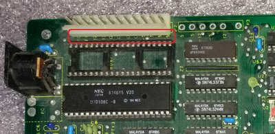
On this picture the rails are labelled. Looks standard AT to me.
But if you want to make 100% sure why not check for continuity with the power pins in the card slots like it's already been suggested?
Thanks for all your help, I'll check continuity when the board arrives.
I have never seen a PSU with a power connector like this so I was naturally curious. I don't like forcing things together to make them fit. It's a common board but not in Hungary. 😁
Famicomaster, I'll post the ROM files once the board gets here and I have a chance to read them with my TL866II+.
Wonder if the BIOS is Phoenix, DTK, or the generic "Turbo XT" clone BIOS. My first one came with Phoenix and my second came with "Turbo XT"
Hoping for the DTK so we can get the trilogy!
Got the ROM files as promised!
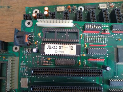
This looks like it's pretty much identical to the XT clone I have. Here's a pic:
I have the original manual which I scanned:
https://www.dropbox.com/s/ova9lr4nf7apmpd/xt- … rboard.zip?dl=0
And here's a link to a thread I had a few years ago on vcfed about building it and pimping it up. Unfortunately most of the links are broken now.
http://www.vcfed.org/forum/showthread.php?484 … ebay-components
It takes a standard AT power supply, though the pins being rounded and not flat it's difficult to plug it in.
I/O, I/O,
It's off to disk I go,
With a bit and a byte
And a read and a write,
I/O, I/O