VOGONS


First post, by parhelia512

User metadata
Rank Member
Rank
Member

Hello eveybody ! Hope you are all fine !

I bought recently a QDI p5i430vx motherboard to build a DOS / Win 9x era retro gaming PC.

1607671611-board.png

It was supposed to work correctly but...again, no luck, the motherboard is not working.

I tried lot of things, changing cards, CPU, checking jumpers...same results : as soon as the AT power button is pressed, power supply stops and nothing happens...something looks shorten.

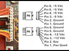
I took my multimeter and, chek the AT power connector without power supply plugged in.

1607671891-pinout-at-power-connectors-01.png

When touching the PIN3 (+12V) connector, it looks connected to the GROUND, which is, if i understand correctly, not correct.

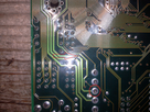
I tried to follow the 12V track at the motherboard back

1607671618-holes.png

And i need your help to understand what's happening...
The track seems easy to follow as it's a large one (due to the high 12V voltage ?)
Following the track, i can see there are smalls holes on the way. Sometimes, i understand that it means the track need to be followed on the other side of the board...sometimes, there is a hole but nothing on the otherside...what's happening ? Is there a not visible track on a not visible layer of the board ?

For what i can see :
The 12V track goes :
- To one PCI slots (i can see the track going to one slot, then i lost the track but other PCI slots are receiving the 12V signal)
- To one ISA slots (same thing, other ISA slots are receiving the 12V signal, but i can't see the track)
- From the ISA slot located at the bottom of the board, the ISA's 12V pin is connected to another 12V track :
. - one part of the track is going to a small capacitor (end of this part of the track ?)
. - other part of the track is going to the +12v fan connector, this one is connected to another small capacitor (end of this part of the track ?)
The +12V fan connector is grounded too...normal.
Both connectors of each capacitor are grounded too...

And the question 😁 Where should i search the short ? I mean the track looks fine, no scratches...the PCI and ISA slots look fine too...no bent pin or metal in the slots...i don't understand where is the short...

Could you help me please ? i'm tired of non working components but, this helps understanding how things are made.

Thanks for your help ! 😀
Reply 1 of 31, by majestyk

User metadata
Rank Oldbie
Rank
Oldbie

Mainboards can have 6 layers easily, not just the traces on the up- and downside.
So there´s a lot going on "underground".

Old tantalum capacitors (mustard coloured here) love to have short circuits. Then there´s zero Ohms between the supply voltage and ground and the PSU won´t power up.
You have to find the one with the short by desoldering the tantalum caps on the respective supply voltage one by one until you find the culprit.

Reply 2 of 31, by parhelia512

User metadata
Rank Member
Rank
Member

Hello majestyk and thank you for your answer.

OK, so this is why i lost some tracks...but i think that "underground" tracks have no reasons to die (except huge scratches) ?

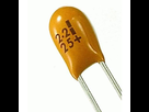
1607678824-tantalum-capacitors-500x500.png

Ok, tantalum capacitors are those strange bubbles...i begin to check one of them because right now, even still connected to the board, it is short so it should be on the 12V track ?
Can i try to start the board without one of these capacitors ?
If I find the culprit, do I have to replace it with another tantalum one ?

Thanks !

Reply 3 of 31, by parhelia512

User metadata
Rank Member
Rank
Member

Ok...so on the +12V track i found this capacitor

1607679582-culprit.png

Unsoldered, it is shorted ! Seems to be the culprit
Now, to read the value...
is 106 meaning 10 * 10^6 pF? so 10µF ?
is 25V or is the "K" meaning something ?

Can i replace it with another type of capacitor ?

Thanks for your help !

Reply 5 of 31, by Tiido

User metadata
Rank l33t
Rank
l33t

One missing cap will not cause problems, especially on 12V which those boards usually don't use for anything but integrated COM ports.

T-04YBSC, a new YMF71x based sound card & Official VOGONS thread about it
Newly made 4MB 60ns 30pin SIMMs ~
mida sa loed ? nagunii aru ei saa 😜

Reply 6 of 31, by parhelia512

User metadata
Rank Member
Rank
Member

Thanks for all your answers !

I replaced the capacitor with another "classic" one with same values from an old broken motherboard.
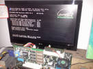
And guess what ???....

1607681589-ok.png

Thank you for your help, and thank you majestyk for pointing the tantalum capacitors, it was an huge help and a huge amount of time saved !

Thank you VOGONS community ! 😀

Reply 7 of 31, by parhelia512

User metadata
Rank Member
Rank
Member

If someone else runs into the same problem, here was the broken capacitor :

1607682234-localisation.png

Hope others tantalum capacitors on the board won't die...something like 20 on the board !

Reply 9 of 31, by evasive

User metadata
Rank Oldbie
Rank
Oldbie

You might want to do a full recap on your board indeed and if not using tantalums make sure you use low-ESR electrolytic capacitors as that is what is mandatory on motherboards.

Reply 10 of 31, by parhelia512

User metadata
Rank Member
Rank
Member

Hello Deksor ! Yes, it's this one !
Isn't the image in the first post good enough ? My phone is from 2009 and i can't do more thant 5 mpixels. But if you want something more detailed (SLOT, Socket...), please ask ! 😀

Hello evasive. Ok, how can i identify low-ESR capacitors ? the one i have used was from a jetway socket 478 mainboard.

Reply 11 of 31, by Deksor

User metadata
Rank l33t
Rank
l33t

It's not the resolution, it's the light and the angle 😀 (actually I can work with images that have an angle like this but they tend to get blurry and lighting tends to be bad. It's the case for both here)

What I tend to do is to put the motherboard on a piece of paper on a table in a room with exterior light coming and then try to shoot the picture with my phone above it while trying to hold it parallel to the motherboard.

Using your phone's flashlight or putting a bright light source above the mobo is a bad idea and will cause lots of glare.

Trying to identify old hardware ? Visit The retro web - Project's thread The Retro Web project - a stason.org/TH99 alternative

Reply 12 of 31, by parhelia512

User metadata
Rank Member
Rank
Member

Ok Deksor, I will try to do this this week end and will post here the picture.
Do I have to remove CPU and memory ?

I have a 486 LPX motherboard that i wasn't able to find in your database nor browsing google (look quite the same as the FIC 486-VA?).
I will take a picture too.

Reply 13 of 31, by evasive

User metadata
Rank Oldbie
Rank
Oldbie
parhelia512 wrote on 2020-12-11, 12:11:

Hello evasive. Ok, how can i identify low-ESR capacitors ? the one i have used was from a jetway socket 478 mainboard.

Recycling from another motherboard is perfectly fine. Just make sure to stay away from the known bad brand capacitors.

Reply 14 of 31, by parhelia512

User metadata
Rank Member
Rank
Member

Hello Deksor,

Here are the pictures of the QDI + unknown 486-VIA motherboard.
Hope the quality will be good enough for you

1607858639-qdi.png

1607858646-486-va.png

Thanks evasive for the advice !

Reply 16 of 31, by parhelia512

User metadata
Rank Member
Rank
Member

I think there isn't enough light as it's a cloudy day !

Yes, it looks really like this FIC but i do not have that much jumpers near the video chipset nor the same connectors on the I/O shield.
I have 2 PS/2 connectors and on your scheme it doesn't look like PS/2 slot ? Am I wrong ?

Your database is GREAT !

Reply 17 of 31, by parhelia512

User metadata
Rank Member
Rank
Member

My board BIOS is an Award one.
I have no jumper to change system bus speed, I need to replace the crystal oscillator for bus modification.
Maybe it's a rebranded FIC ? On the board I have what seems to be Hyunday stickers (same on the floppy, hard drive, power supply)...Sadly I don't have the original case 😒

Reply 18 of 31, by Deksor

User metadata
Rank l33t
Rank
l33t

The connectors may not physically look the same, but it's just a mistake/lazyness on Microhouse's side. If you look what these connectors are doing, they're what you expect (CN6 is VGA, the "at keyboard connector" is just the keyboard's connector, etc)

However you're correct about the video jumpers not matching. Moreover in the jumper manual there's "86C805" mentioned which tells us it's using a S3 video chip. Yours is using a cirrus logic.
Maybe that's why your board says "486-VA" and this one says "486-VAL".
They must be close relatives. Maybe evasive has more infos about this one ?

Trying to identify old hardware ? Visit The retro web - Project's thread The Retro Web project - a stason.org/TH99 alternative

Reply 19 of 31, by evasive

User metadata
Rank Oldbie
Rank
Oldbie

Not on this particular board but I know there is the 486-vac-v which is also LPX, has onboard CL video as well but a different layout. I'll have another dive at the archives and I will add have added that one to UH19 as well.
https://www.ultimateretro.net/en/motherboards/6898

I was operating at "D" for adding chipsets, otherwise I might have seen this one sooner.

Last edited by evasive on 2021-11-28, 14:15. Edited 1 time in total.