VOGONS


First post, by majestyk

User metadata
Rank Oldbie
Rank
Oldbie

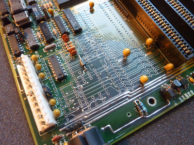
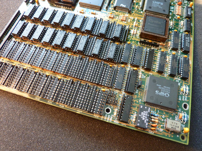
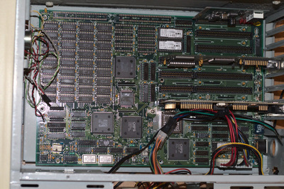
I recently found this mainboard in quite poor condition. It showed the typical Varta battery havoc, numerous components were missing and many many solderings were broken - probably due to some baseball bat treatment.
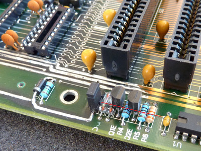
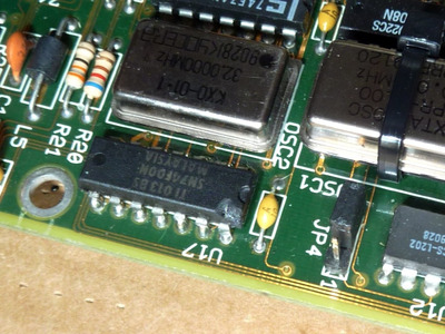
Capacitors were broken, resistors also, the second oscillator, all jumpers, and some tantalums were missing plus there was corrosion everywhere.

neat_sx1.jpg
Filename
neat_sx1.jpg
File size
376.6 KiB
Views
1642 views
File license
Fair use/fair dealing exception

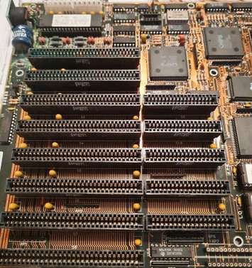
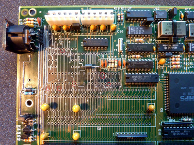
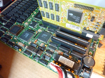
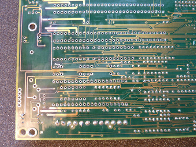
After a complete and intensive cleaning all components in the contaminated area had to be removed so I could remove the battery leakage, the undermined mainboard coating and all oxidations / corrosions on the copper traces.

neat_sx_2.JPG
Filename
neat_sx_2.JPG
File size
793.02 KiB
Views
1642 views
File license
Fair use/fair dealing exception

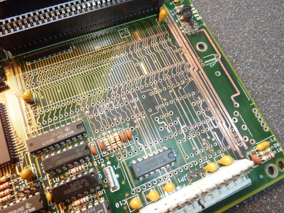
The backside was treated respectively.

neat_sx_3.JPG
Filename
neat_sx_3.JPG
File size
766.14 KiB
Views
1642 views
File license
Fair use/fair dealing exception

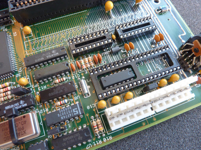
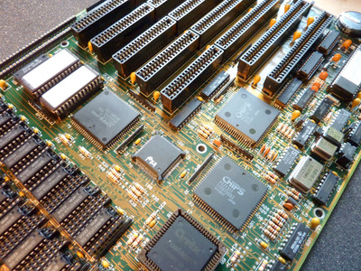
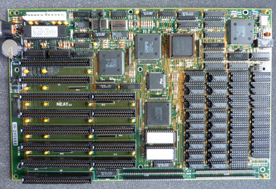
Meanwhile I discovered that several (nearly all) pins of the (16 MHz) 386 CPU were loose. Also each and every chip of the "Chips and Technology" NEAT components had lots of loose solderings.

neat_sx_cpu.JPG
Filename
neat_sx_cpu.JPG
File size
229.58 KiB
Views
1642 views
File license
Fair use/fair dealing exception
neat_sx_cpu2.JPG
Filename
neat_sx_cpu2.JPG
File size
258.58 KiB
Views
1642 views
File license
Fair use/fair dealing exception

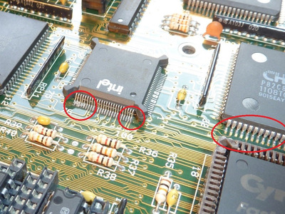
ALL pins of the CPU and all pins of the 4 chipset chips had to be resoldered carefully.

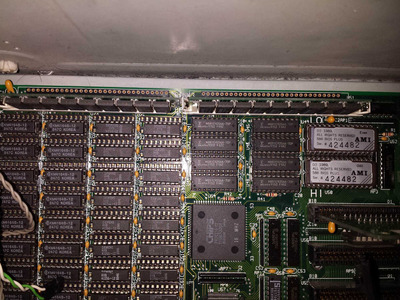
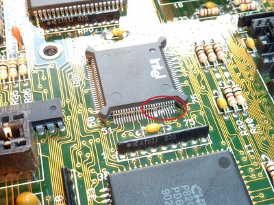
I could NOT find a trace leading to the CPU´s "LOCK#" pin (Pin 26).
I´m not sure if this has never been connected or if the trace was simply ripped away by the unknown mainboard abuser. Any information on this would be welcome!

Last edited by majestyk on 2021-04-01, 19:15. Edited 5 times in total.

Reply 1 of 45, by majestyk

User metadata
Rank Oldbie
Rank
Oldbie

Then I replaced all the broken / missing components and gave the damaged traces a clean and shiny tin-coating.
The traces for power supply got an additional wire attached.

neat_sx_4.JPG
Filename
neat_sx_4.JPG
File size
1.59 MiB
Views
1637 views
File license
Fair use/fair dealing exception

When measuring all the single traces I found a lot of interruptions (red marks):

interrupted_traces.jpg
Filename
interrupted_traces.jpg
File size
1.73 MiB
Views
1637 views
File license
Fair use/fair dealing exception

All of them got repaired with thin wires and a good magnifying glass.
I also found an interrupted trace that lies under the components of the charging circuit.

charger_circuit.JPG
Filename
charger_circuit.JPG
File size
583.81 KiB
Views
1637 views
File license
Fair use/fair dealing exception

Now the reconstruction work could begin, starting with the smaller components.

neat_sx_5.JPG
Filename
neat_sx_5.JPG
File size
1.9 MiB
Views
1637 views
File license
Fair use/fair dealing exception

Today i inserted the 3 missing chips in their sockets, the two BIOS chips and the keyboard controller.
(pictures to follow)

Then I was in the mood to turn the whole thing on. -> nothing.
The PSU didn´t start, a shorted tantalum in the -12V line was the culprit. After that the sytem started for a few seconds, then it shut down again. Shorted tantalum in the +12V line had to be raplaced also.
Then, finally a sign of life!

neat_sx_posting.jpg
Filename
neat_sx_posting.jpg
File size
141.26 KiB
Views
1637 views
File license
Fair use/fair dealing exception

The "1131" in the BIOS-string identifies this mainboard as an ECS/Elitegroup model.

to be continued...

Reply 2 of 45, by majestyk

User metadata
Rank Oldbie
Rank
Oldbie

This NEATsx seems ready for it´s second life now. It´s running stable, all 8 and 16 Bit ISAs are functional again, I can boot into DOS and run the usual tests - no problems so far.

I´ll have to get some additional RAM, 4MB onboard RAM should be o. k.
Sockets for SIMMS can´t be installed here, because the 4 connectors at the bottom don´t have enough distance between them. So I could install another 4MB SIPP-RAM, that I don´t have.

neatsx6.JPG
Filename
neatsx6.JPG
File size
1.9 MiB
Views
1572 views
File license
Fair use/fair dealing exception
neatsx7.JPG
Filename
neatsx7.JPG
File size
1.75 MiB
Views
1572 views
File license
Fair use/fair dealing exception
neatsx9.JPG
Filename
neatsx9.JPG
File size
1.5 MiB
Views
1572 views
File license
Fair use/fair dealing exception
neatsx8.JPG
Filename
neatsx8.JPG
File size
199.23 KiB
Views
1572 views
File license
Fair use/fair dealing exception

There are still some cosmetic repairs to be made, since this board has been treated with brutality.
How do you damage an integrated circuit?

neatsx10.JPG
Filename
neatsx10.JPG
File size
174.07 KiB
Views
1572 views
File license
Fair use/fair dealing exception

By dropping a hammer on it.

Last edited by majestyk on 2021-04-02, 17:54. Edited 1 time in total.

Reply 3 of 45, by weedeewee

User metadata
Rank l33t
Rank
l33t

It's the same board as I have it only supports 8MB RAM. 4MB in the SIPP slots, and 4M for the DIP sockets. I tried with 4M modules, 9chips, 3chips, didn't work.

Right to repair is fundamental. You own it, you're allowed to fix it.
How To Ask Questions The Smart Way
Do not ask Why !
https://www.vogonswiki.com/index.php/Serial_port

Reply 4 of 45, by majestyk

User metadata
Rank Oldbie
Rank
Oldbie

The DIL sockets - according to the documentation I could find - can be populated with "411000" chips (36 in total in Banks 0 and 1 including parity). That´s (1048 x 1) / 8 = 131 per chip x 32 chips = 4192 that´s 4MB.

Not so sure about the 4MB in the SIPP slots. 4x9 chips is for sure due to the parity chip.
The chips´ timings should be fast enough to run them with zero wait states.

Btw, the jumper settings on Stason and related have the CPU clock setting wrong.
So if you have the 16MHz version and a faster math-proc and second oscillator (40MHz) are installed, and you jumper "JP2" 2-3 according to to Stason (CPU Osc.2) then your 16 MHz cpu will run with Osc1 at 20 MHz. It´s getting considerable hotter then and probably unstable under load. Plus the (Chips and Technology) 82C811 on the 16 MHz boards is not built for 20 MHz.
The 20 MHz version of the NEATsx has 82C211 with a "20 MHz" stamp on it.
Since this chipset (CS8221) was originally a 286 chipset for 12 and 16 MHz the 20MHz version must be different or selected for this higher frequency.

Last edited by majestyk on 2021-04-02, 17:34. Edited 1 time in total.

Reply 5 of 45, by weedeewee

User metadata
Rank l33t
Rank
l33t

maybe I didn't make myself clear, 4MB modules in the sipp sockets do not work.

I tried to make complete sense of the memory layout described in the total hardware/microhouse documentation, but meh, seems odd.
Since I lack any DIP packages of DRAM, I was thinking of just wiring some simms to the dip sockets but haven't gotten around to it yet. Would be nice to have some spare simm sockets but... oh I salvaged a pair from a 486 board which had a nasty battery leak. something to add to the to do list.
about the clock jumper, yep, noticed that too, though, only a 16MHz cpu here.
I think there was another jumper mismatch as well... can't recall.

Enjoy your board 😀

Right to repair is fundamental. You own it, you're allowed to fix it.
How To Ask Questions The Smart Way
Do not ask Why !
https://www.vogonswiki.com/index.php/Serial_port

Reply 6 of 45, by majestyk

User metadata
Rank Oldbie
Rank
Oldbie

I also tried with two 4MB sticks - the board wouldn´t start.

I will test this board in the coming weeks. Although I´m not a big fan of ECS / Elitegroup (and never was) I kept some of the earlier boards like the "SI5PI AIO" socket 4 and the "SI54P-AIO" socket 5. The quality was absolutely o.k. at that time. Later it turned really ugly.

Reply 8 of 45, by majestyk

User metadata
Rank Oldbie
Rank
Oldbie

You can set the time / date and drives in main "CMOS SETUP" 😀

neatsx11.JPG
Filename
neatsx11.JPG
File size
187.04 KiB
Views
1504 views
File license
Fair use/fair dealing exception

Everything else is to be found in "XCMOS SETUP":
1. "Easy Neat Chipset Register Setup"

neatsx12.JPG
Filename
neatsx12.JPG
File size
165.29 KiB
Views
1504 views
File license
Fair use/fair dealing exception

and
2. Advanced Neat Chipset Register Setup"

neatsx13.JPG
Filename
neatsx13.JPG
File size
160.69 KiB
Views
1504 views
File license
Fair use/fair dealing exception

That´s where you must know what you´re doing. Fortunately there are some 286 mainboard manuals with this chipset still available online.

Reply 9 of 45, by Deksor

User metadata
Rank l33t
Rank
l33t
majestyk wrote on 2021-04-02, 17:42:

I also tried with two 4MB sticks - the board wouldn´t start.

I will test this board in the coming weeks. Although I´m not a big fan of ECS / Elitegroup (and never was) I kept some of the earlier boards like the "SI5PI AIO" socket 4 and the "SI54P-AIO" socket 5. The quality was absolutely o.k. at that time. Later it turned really ugly.

They were decent before they merged with PCChips by the late 90's. After that, yes the quality of their PCB dropped dramatically. But up to their 486 and perhaps early pentiums they were great.

Trying to identify old hardware ? Visit The retro web - Project's thread The Retro Web project - a stason.org/TH99 alternative

Reply 10 of 45, by Schule04

User metadata
Rank Member
Rank
Member
majestyk wrote on 2021-04-02, 18:23:

That´s where you must know what you´re doing. Fortunately there are some 286 mainboard manuals with this chipset still available online.

Did you find a manual for the memory settings in the BIOS? I have a very similar board also with no jumpers:

_MG_1000_01.jpg
Filename
_MG_1000_01.jpg
File size
1.11 MiB
Views
1469 views
File license
Public domain

The BIOS looks the same as yours, except for the manufacturer string which shows that this is a Seritech board. I wonder how the memory could be upgraded from the 640K on board.

Reply 11 of 45, by weedeewee

User metadata
Rank l33t
Rank
l33t
majestyk wrote on 2021-04-02, 17:42:

I also tried with two 4MB sticks - the board wouldn´t start.

I will test this board in the coming weeks. Although I´m not a big fan of ECS / Elitegroup (and never was) I kept some of the earlier boards like the "SI5PI AIO" socket 4 and the "SI54P-AIO" socket 5. The quality was absolutely o.k. at that time. Later it turned really ugly.

Dito, ECS, pcchips and several other names that were the same manufacturer but different brandname. I'm also very suspicious about anything asrock.

Right to repair is fundamental. You own it, you're allowed to fix it.
How To Ask Questions The Smart Way
Do not ask Why !
https://www.vogonswiki.com/index.php/Serial_port

Reply 12 of 45, by weedeewee

User metadata
Rank l33t
Rank
l33t
majestyk wrote on 2021-04-02, 18:23:

2. Advanced Neat Chipset Register Setup"

If i'm not mistaken, every register has a one line description, and the "Easy Neat Chipset Register Setup" settings are also listed here

Right to repair is fundamental. You own it, you're allowed to fix it.
How To Ask Questions The Smart Way
Do not ask Why !
https://www.vogonswiki.com/index.php/Serial_port

Reply 13 of 45, by weedeewee

User metadata
Rank l33t
Rank
l33t
Schule04 wrote on 2021-04-02, 20:06:
Did you find a manual for the memory settings in the BIOS? I have a very similar board also with no jumpers: […]
Show full quote
majestyk wrote on 2021-04-02, 18:23:

That´s where you must know what you´re doing. Fortunately there are some 286 mainboard manuals with this chipset still available online.

Did you find a manual for the memory settings in the BIOS? I have a very similar board also with no jumpers:

_MG_1000_01.jpg

The BIOS looks the same as yours, except for the manufacturer string which shows that this is a Seritech board. I wonder how the memory could be upgraded from the 640K on board.

http://www.win3x.org/uh19/motherboard/show/2100

You have one bank full of 64kbit chips, another full with 256kbit chips, for a total of... 640KB
It's a 386SX, which has a 16 bit memory bus and requiring parity. 18 64kbit chips and 18 256kbit chips.

Easiest you could do is find yourself four 30 pin sipp modules. and upgrade it to 4 MB + 640KB.
pretty sure you'll need 9 chips per module, I didn't succeed in finding any 3 chip modules to work on the neatsx board.
Other option would be find yourself 4 simm sockets, break off on side and stick them in the sipp sockets.
You might have to thicken the pins of the simm sockets by putting some solder on them, just a lick.
Then you can insert four simms with 9 chips each into the simm sockets.
Or you can try and solder pins to the simm modules.
Fourth option would be to find 36 1Mbit chips and replace all the chips in the dip sockets.
Enjoy .

edit, from the looks of the board you might not have to cut a side of a simm socket like I had to do on mine. Seems like your board has them separated far enough from each other.

Right to repair is fundamental. You own it, you're allowed to fix it.
How To Ask Questions The Smart Way
Do not ask Why !
https://www.vogonswiki.com/index.php/Serial_port

Reply 14 of 45, by majestyk

User metadata
Rank Oldbie
Rank
Oldbie

First of all the build quality of this early Elitegroup mainboard is excellent, (with a little help) It has survived many years of abuse and brutality a n d it overcame the VARTA pest.
You can also see and feel the quality when working on it.

neatsx15.JPG
Filename
neatsx15.JPG
File size
1.82 MiB
Views
1364 views
File license
Fair use/fair dealing exception

Both ways, acquiring 36 1Mx1 chips and finding 4 9chip SIPPS turn out to be quite expensive and difficult - even today.
The best option is to fit in 4 30 pin SIMM sockets IF the board supports it like the Seritech seems to do and then use standard 30 pin SIMMS with 9 chips and 1MB each.

I couldn´t agree more witch you, weedeewee, on the ASROCK issue. But still - as in the case of PC Chips - there are several people reporting good experiences...
(ASROCK can´t be put in the same category as PC Chips though.)

What could be the purpose of the 8 DIL20 sockets "U41 - U48" on the Seritech board?? Is this for additional parity chips for the SIPP slots when sticks without parity are installed?

At the moment I cant´t find a complete copy of the 286 NEAT chipset mainboard manual I mentioned. Copies like this
http://www.minuszerodegrees.net/manuals/NEAT- … rs%20Manual.pdf
are missing pages 16 - 21 and that´s exactly the pages where the chipset registers for the single chips should be documented.

Reply 15 of 45, by Schule04

User metadata
Rank Member
Rank
Member

Yep, I already got some SIMM sockets and 1M SIMMS with 9 chips to use with the board. The SIMM holder does not fit sadly so I had to remove the end of one of them. But either these modules are not compatible with the board or there is no good connection, because when I insert them the POST code gets stuck at 04 forever. I also tried inserting the sticks the other way around, then I get random beeping and POST codes. I guess the solder trick to thicken the legs will be worth a try.

Reply 17 of 45, by Schule04

User metadata
Rank Member
Rank
Member

There is only one jumper on my board, the rest are labeled as jacks. The JP1 seems to be for clearing the CMOS and maybe activating an external battery. All the memory settings have to be configured inside the extended CMOS. But when I enable the banks 2+3 there the board stops POSTing properly.

I suspect it can also detect the memory size automatically because it enables 640K even when it's not set up for that amount, and because it acts differently when something is in the SIPP slots

Reply 18 of 45, by majestyk

User metadata
Rank Oldbie
Rank
Oldbie

That´s odd. I´m still wondering what U41 - U48 are for.
Both mainboards are using the same MCH (82C812), have the same architecture for the DIP-RAMs and still there seems to be some difference (the manual could probably tell us about).
Maybe the Seritech is designed to use 8-chip SIMMS and Parity must be populated onboard in the vacant 8 sockets. There seem to be a lot of traces leading from U41-U48 to the SIPP slots.

Reply 19 of 45, by Schule04

User metadata
Rank Member
Rank
Member

Seems like it really is needed for parity. I've now put some RAM (type MB81C4256A-70p) from a 286 board in the empty sockets, and it boots and recognizes the two 1MB SIMMs, the onboard 640K plus an additional 256K.

IMG_20210404_001724.jpg
Filename
IMG_20210404_001724.jpg
File size
413.71 KiB
Views
1302 views
File license
Public domain
IMG_20210404_001704.jpg
Filename
IMG_20210404_001704.jpg
File size
599.89 KiB
Views
1302 views
File license
Public domain

The SIMMs are really loose, I guess I'll get some pin headers and convert it to SIPP.

EDIT: The bios counts up to 2,9MB, but the bios menus and POST screen now only say 512KB base memory and do not find the 64K type memory chips. hmmm....
Seems like this chipset can only use the 64kbit chips in the 640KB configuration, and will ignore them when more RAM is present. I guess I'll either have to upgrade the chips to 256kbit ones or remove all DIPPs to get 640K base memory? Or are these boards limited to 512K? That would seriously suck

IMG_20210404_01453d9.jpg
Filename
IMG_20210404_01453d9.jpg
File size
582.63 KiB
Views
1291 views
File license
Public domain