Hi everybody !
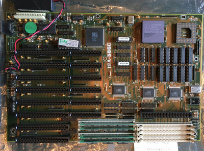
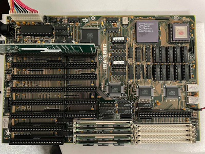
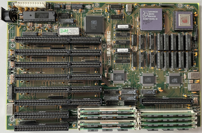
I've obtained this extra cool ASUS ISA-386C mainboard 😀
Unfortunately, all the crystal oscillators are missing.... but I have to try to make it work.
What should be the frequency of the oscillator near ISA sockets ?
The frequency of this one is not shown on PCB 🙁
Hate posting a reply and then have to edit it because it made no sense 😁 First computer was an IBM 3270 workstation with CGA monitor. Stuff: https://archive.org/details/@horun
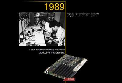
Locutuswrote on 2021-08-28, 00:10:Looks like there are some versions. Mine looks like the one form ASUS poster...
ASUS_PIC.jpg […] Show full quote
Looks like there are some versions. Mine looks like the one form ASUS poster...
ASUS_PIC.jpg
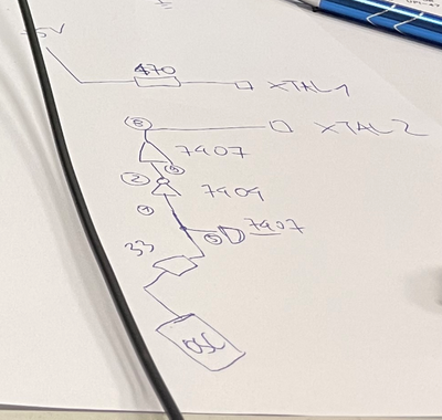
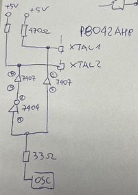
This oscilator 'clocks' XTAL2 of the P8042AHP.
The guy I got it from said that it was 80MHz oscilator... but I've got some doubts...
image_2021-08-28_021737.png
Yep Mine is v1.1, yours is v1.0 (printed between the ISA slots.)
So it runs up to the KB controller after going thru logic up by the 85c206 ? Saw your drawing and it of makes no sense (not your fault) but to run a clock circuit that far to logic then back to the KBC just seems odd.
Am probably mis-reading what you meant but that just seems out of spec and not a normal way to do things.
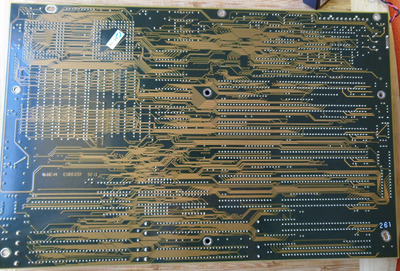
Can you take a good picture of the back of your board ?
Hate posting a reply and then have to edit it because it made no sense 😁 First computer was an IBM 3270 workstation with CGA monitor. Stuff: https://archive.org/details/@horun
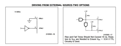
Well the datasheet for the P8042 gives the min/max clock period as 80 & 613 ns. Which I think works out as 12.5MHz down to 1.63MHz. So that narrows it down a bit. Looks like they might be using the second clock input circuit from the datasheet:
Yep Mine is v1.1, yours is v1.0 (printed between the ISA slots.)
So it runs up to the KB controller after going thru logic up by the 85c206 ? Saw your drawing and it of makes no sense (not your fault) but to run a clock circuit that far to logic then back to the KBC just seems odd.Am probably mis-reading what you meant but that just seems out of spec and not a normal way to do things.
Can you take a good picture of the back of your board ?
Sorry, english is my second language so....
That seems odd to me too, but I've tracked connections from the PCB .
Well the datasheet for the P8042 gives the min/max clock period as 80 & 613 ns. Which I think works out as 12.5MHz down to 1.63MHz. So that narrows it down a bit. Looks like they might be using the second clock input circuit from the datasheet:P8042_Clock.jpg
Exactly my point - that's why I've asked.... but I'm a 'hothead' so the storry continues fast.... 😉
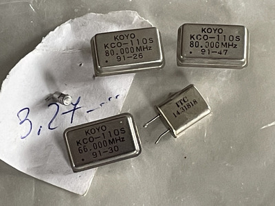
This is the bag of oscillators that I got with the mainboard. The guy I got it from is a ham radio enthusiast... he took out oscillators 25years ago and (Thank God) forgot to trash the rest...
He is 100% positive that this is the set from this motherboard (they turned out not so useful after all...).
Batch dates on them seem to confirm his words.
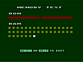
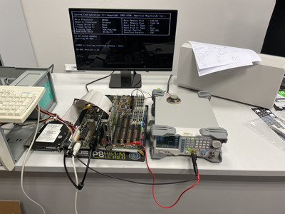
1) The mainboard 'gave signs of life' 😉
It showed BIOS version and stopped on memory test (sometimes counted 64k..... of RAM after power on but in most cases nothing at all) and made a reset (in infinite loop)
2) To be sure I've mounted 100% verified RAM and CPU and removed FPU (same behavior).
3) I took out keyboard controller (8042AHP) and without it, the mainboard starts, tests all installed RAM and freezes with constant beep where it should display 'Press ....'(quite normal right ?).
So... I've returned to this 'enigmatic' oscillator.
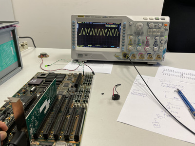
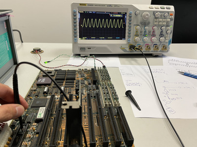
Signal on the output (capacitance of the probe makes it look like sine).
Yep ! The 7404 is an inverter and 7407 is a buffer, no flip-flops/dividers if you traced accurate.
Sounds like you need a ~8Mhz crystal. Not 80Mhz.
Hate posting a reply and then have to edit it because it made no sense 😁 First computer was an IBM 3270 workstation with CGA monitor. Stuff: https://archive.org/details/@horun
Great ! added: I think you want a DOC 20 or DOC 70 type crystal (case size 14pin, TTL output)
Hate posting a reply and then have to edit it because it made no sense 😁 First computer was an IBM 3270 workstation with CGA monitor. Stuff: https://archive.org/details/@horun


