appiah4 wrote on 2023-06-16, 18:41:
What could cause a Keyboard error yet a working keyboard? Perhaps this board doesn't like my PS2 keyboard through an AT adapter?
PS/2 and AT is really just a different pinout. IBM shrunk both connectors when they added the second connector for the mouse. As long as your adapter isn't generally broken, it's not the source of your issue. As typing works, we can be sure that both the DATA and the CLK lines are connected. Also, +5V and GND also obviously work, because otherwise the keyboard wouldn't be powered at all.
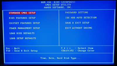
As I already said, both DATA and CLK in the keyboard protocol are bidirectional. The AT keyboard protocol supports communication in both directions: The host can send commands to the keyboard. The keyboard can send command responses to the host and the keyboard can send information about the keys you pressed to the host. Obviously, the keyboard sending key codes to the host works. Key codes and command responses are sent the same way, so if one kind of communication from the keyboard to the host works, the other one works, too. This leaves communication from the host to the keyboard as the final unknown. When you boot up the machine, the BIOS instructs the keyboard controller to send a "reset" command to the keyboard, and expects to receive a "keyboard passed the keyboard POST" response. Also, the BIOS sends an "identify keyboard type" command (to find out whether it is an original AT 84-key keyboard or an enhanced 101/102-key keyboard), and expects a response to that command. Possibly, sending commands to the keyboard fails, and the BIOS notices that the keyboard doesn't respond to the commands it tries to send. The only issue I see with this theory is that non-working command transfer to the keyboard means that the "start sending key codes" command won't reach the keyboard. It's not impossible that your keyboard powers up with sending key codes enabled, though.
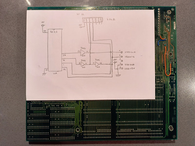
There is a quick way to test whether sending commands to the keyboard works: The indicator LEDs (NUM, CAPS, SCROLL) are host-controlled using the "set LEDs" command. If pressing NUM LOCK doesn't toggle the LED, I'm on to something. If sending command indeed doesn't work, the primary suspect are the traces from pins 37 and 38 of the KBC to the 7406 and the traces from the 7406 to pins 1 and 39 of the KBC, as well as the power supply pins of the 7406. The 7406 is only required to send stuff to the keyboard, but not to receive stuff from the keyboard.