VOGONS


[SOLVED] Keyboard + mouse connectors problem

Topic actions

Reply 20 of 88, by weedeewee

User metadata
Rank l33t
Rank
l33t

erhm
750W Heißluftpistole und einem 60W Lötkolben
ok.
I mean the carbonized parts weren't visible on the first photo.

What temperature do you have both set at ?
I'm assuming you're using the Iron, not the hot air part to solder.

Right to repair is fundamental. You own it, you're allowed to fix it.
How To Ask Questions The Smart Way
Do not ask Why !
https://www.vogonswiki.com/index.php/Serial_port

Reply 23 of 88, by boby

User metadata
Rank Member
Rank
Member
weedeewee wrote on 2024-01-01, 19:09:
erhm 750W Heißluftpistole und einem 60W Lötkolben ok. I mean the carbonized parts weren't visible on the first photo. […]
Show full quote

erhm
750W Heißluftpistole und einem 60W Lötkolben
ok.
I mean the carbonized parts weren't visible on the first photo.

What temperature do you have both set at ?
I'm assuming you're using the Iron, not the hot air part to solder.

Yes, using iron to desolder, 375 celsius temp. Saw that value in one tutorial 🙂

Reply 24 of 88, by DerBaum

User metadata
Rank Oldbie
Rank
Oldbie
boby wrote on 2024-01-01, 19:39:
weedeewee wrote on 2024-01-01, 19:09:
erhm 750W Heißluftpistole und einem 60W Lötkolben ok. I mean the carbonized parts weren't visible on the first photo. […]
Show full quote

erhm
750W Heißluftpistole und einem 60W Lötkolben
ok.
I mean the carbonized parts weren't visible on the first photo.

What temperature do you have both set at ?
I'm assuming you're using the Iron, not the hot air part to solder.

Yes, using iron to desolder, 375 celsius temp. Saw that value in one tutorial 🙂

if i am careful i use 250c and if the pcb is thicker or iam soldering ground i use 300c. my iron has 60 watts.
just to give you some numbers...

FCKGW-RHQQ2

Reply 25 of 88, by boby

User metadata
Rank Member
Rank
Member
DerBaum wrote on 2024-01-01, 19:41:
boby wrote on 2024-01-01, 19:39:
weedeewee wrote on 2024-01-01, 19:09:
erhm 750W Heißluftpistole und einem 60W Lötkolben ok. I mean the carbonized parts weren't visible on the first photo. […]
Show full quote

erhm
750W Heißluftpistole und einem 60W Lötkolben
ok.
I mean the carbonized parts weren't visible on the first photo.

What temperature do you have both set at ?
I'm assuming you're using the Iron, not the hot air part to solder.

Yes, using iron to desolder, 375 celsius temp. Saw that value in one tutorial 🙂

if i am careful i use 250c and if the pcb is thicker or iam soldering ground i use 300c. my iron has 60 watts.
just to give you some numbers...

👍

How do you remove solder from the pin hole? I have removed it everywhere, but on 2 pins. I add more soldering wire and then I use copper to remove it. But somehow, on 2 pins it's stuck and can't remove the port because of it.

Reply 26 of 88, by DerBaum

User metadata
Rank Oldbie
Rank
Oldbie
boby wrote on 2024-01-01, 19:50:
DerBaum wrote on 2024-01-01, 19:41:
boby wrote on 2024-01-01, 19:39:

Yes, using iron to desolder, 375 celsius temp. Saw that value in one tutorial 🙂

if i am careful i use 250c and if the pcb is thicker or iam soldering ground i use 300c. my iron has 60 watts.
just to give you some numbers...

👍

How do you remove solder from the pin hole? I have removed it everywhere, but on 2 pins. I add more soldering wire and then I use copper to remove it. But somehow, on 2 pins it's stuck and can't remove the port because of it.

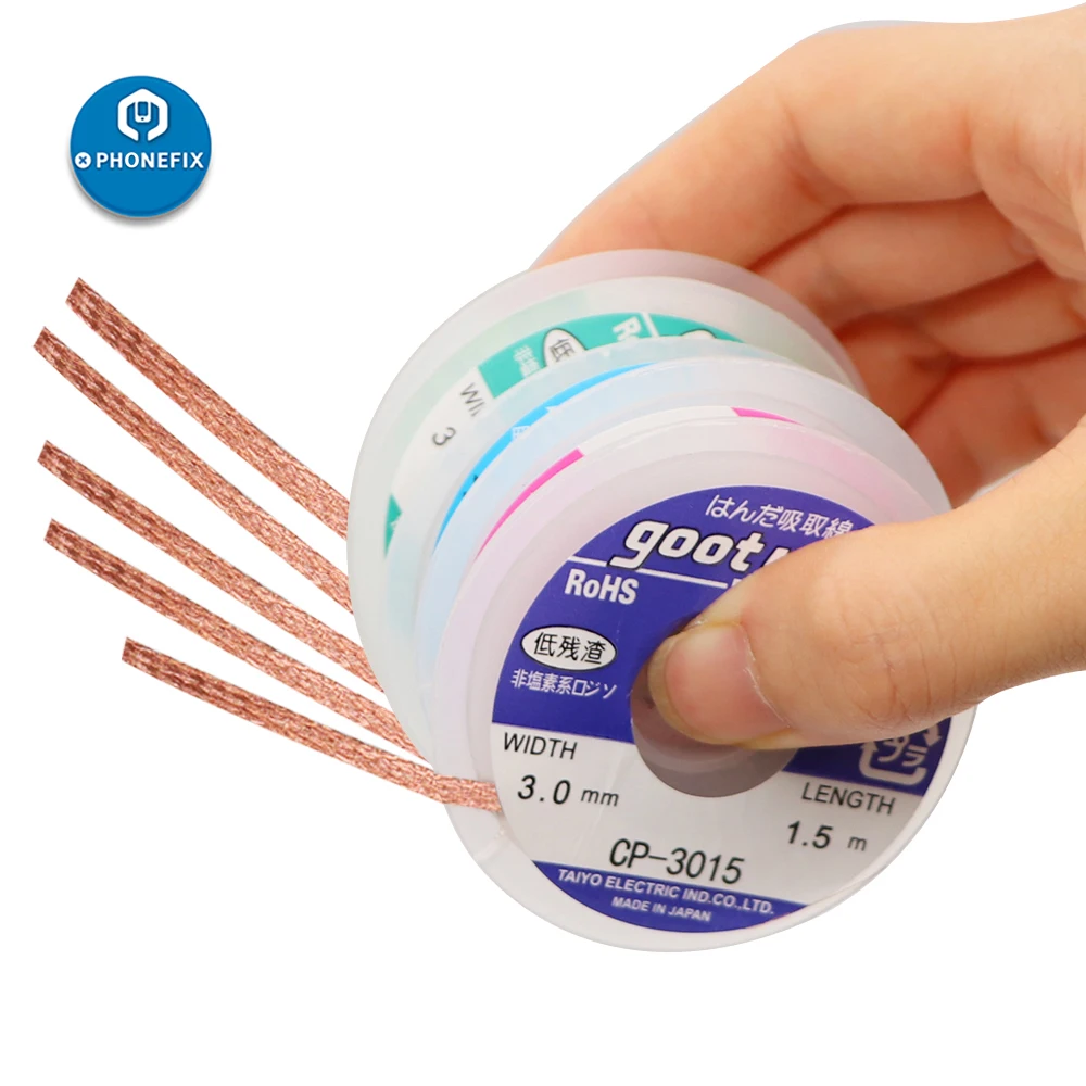
i have a manual solder sucker and i have solder wick...
first remove large amounts with the sucker and then wick it clean to not waste more then neccesary...

51y2sFhV3DL._AC_UF894,1000_QL80_.jpg

5-st-cke-Goot-Docht-Solder-Docht-Entferner-BGA-Abl-tgeflecht-Draht-Sucker-L-ten-Zubeh.jpg

FCKGW-RHQQ2

Reply 28 of 88, by DerBaum

User metadata
Rank Oldbie
Rank
Oldbie
boby wrote on 2024-01-01, 20:15:

I tried with wick and that sucker, but there is still some left. Maybe if I cut pins it will be easier

with 375c you have instantly burnt away all the flux from the flux core. if the solder desnt flow like it should add flux.

And ground holes are especially hard to clean because the large copper surfaces take away all the heat. that is the point where the thermal mass of your iron gets important... transfer all the heat inside the board and not just burn the surface in the beginning and then cool down so much it cant melt the solder anymore...

FCKGW-RHQQ2

Reply 29 of 88, by boby

User metadata
Rank Member
Rank
Member
DerBaum wrote on 2024-01-01, 20:26:
boby wrote on 2024-01-01, 20:15:

I tried with wick and that sucker, but there is still some left. Maybe if I cut pins it will be easier

with 375c you have instantly burnt away all the flux from the flux core. if the solder desnt flow like it should add flux.

And ground holes are especially hard to clean because the large copper surfaces take away all the heat. that is the point where the thermal mass of your iron gets important... transfer all the heat inside the board and not just burn the surface in the beginning and then cool down so much it cant melt the solder anymore...

Good points! Thx!

Reply 30 of 88, by rasz_pl

User metadata
Rank l33t
Rank
l33t
boby wrote on 2024-01-01, 18:52:

Should be 750W here is the link:
https://amzn.eu/d/4VY02r9
Soldering wire is 0.6mm also bought on amazon

Hakko 903 clone tips, 936 clone. Technology from the seventies (1979). Good for soldering wires together or some every basic thru hole from the eighties, bad bad baad for modern multi layer pcbs. It has very little thermal capacity and slow regulation forcing you to use excessive temperature setting to get anywhere. If you dont know what you are doing you will struggle with big components while burning small ones. One common mistake everyone inexperienced makes is using small tip for small components. Small tip means small thermal mass, that only works with excellent soldering irons (oki/metcal, JBC). With above garbage you need
1 skill
2 flux
3 big tip

When I say buy/use flux I dont mean flux inside the solder, I mean
https://termopasty.pl/en/products/solder-paste/ or at the very least colophony Rosin https://en.wikipedia.org/wiki/Rosin. Stuff wets everything properly and makes solder flow into place on its own.
Paste/flux will also let you know your temperature is set too high, if it instantly burns off you went too high.

boby wrote on 2024-01-01, 19:50:

How do you remove solder from the pin hole? I have removed it everywhere, but on 2 pins. I add more soldering wire and then I use copper to remove it. But somehow, on 2 pins it's stuck and can't remove the port because of it.

from best to worse options:
- soldering vacuum gun, >$100 and of little/no use to anyone not doing repairs on a daily basis. Its like buying compressor and spray gun to paint a bicycle fender once.
- skilled person will just use hotair, unskilled person would burn and melt everything around before solder actually melts.
- $5 solder sucker, never liked those but they do work after practice.
- use biggest tip you have so it touches both pins at the same time while pulling on the port from other side.
- cut a used (soaked in solder) piece of soldering braid the size covering both pins, lay it on top of both pins and melt it into them while pulling on the port from the bottom.

But in general if you keep learning how to solder on this board you will end up with unfixable board 🙁

Open Source AT&T Globalyst/NCR/FIC 486-GAC-2 proprietary Cache Module reproduction

Reply 31 of 88, by boby

User metadata
Rank Member
Rank
Member
rasz_pl wrote on 2024-01-02, 01:00:
Hakko 903 clone tips, 936 clone. Technology from the seventies (1979). Good for soldering wires together or some every basic thr […]
Show full quote
boby wrote on 2024-01-01, 18:52:

Should be 750W here is the link:
https://amzn.eu/d/4VY02r9
Soldering wire is 0.6mm also bought on amazon

Hakko 903 clone tips, 936 clone. Technology from the seventies (1979). Good for soldering wires together or some every basic thru hole from the eighties, bad bad baad for modern multi layer pcbs. It has very little thermal capacity and slow regulation forcing you to use excessive temperature setting to get anywhere. If you dont know what you are doing you will struggle with big components while burning small ones. One common mistake everyone inexperienced makes is using small tip for small components. Small tip means small thermal mass, that only works with excellent soldering irons (oki/metcal, JBC). With above garbage you need
1 skill
2 flux
3 big tip

When I say buy/use flux I dont mean flux inside the solder, I mean
https://termopasty.pl/en/products/solder-paste/ or at the very least colophony Rosin https://en.wikipedia.org/wiki/Rosin. Stuff wets everything properly and makes solder flow into place on its own.
Paste/flux will also let you know your temperature is set too high, if it instantly burns off you went too high.

boby wrote on 2024-01-01, 19:50:

How do you remove solder from the pin hole? I have removed it everywhere, but on 2 pins. I add more soldering wire and then I use copper to remove it. But somehow, on 2 pins it's stuck and can't remove the port because of it.

from best to worse options:
- soldering vacuum gun, >$100 and of little/no use to anyone not doing repairs on a daily basis. Its like buying compressor and spray gun to paint a bicycle fender once.
- skilled person will just use hotair, unskilled person would burn and melt everything around before solder actually melts.
- $5 solder sucker, never liked those but they do work after practice.
- use biggest tip you have so it touches both pins at the same time while pulling on the port from other side.
- cut a used (soaked in solder) piece of soldering braid the size covering both pins, lay it on top of both pins and melt it into them while pulling on the port from the bottom.

But in general if you keep learning how to solder on this board you will end up with unfixable board 🙁

I do have a paste flux, not the one from soldering wire.

So my iron is garbage? What should I buy? I know how to spend $500 but I would like not to.

I will practice on something else first not to damage the board even more.

Btw. My board is from 90's, so not too modern. 🙂

I was using small tip on my iron. Thx for the advice.

I also have some cheep 50W soldering iron. Is it better then the current one?

Attachments

Reply 32 of 88, by DerBaum

User metadata
Rank Oldbie
Rank
Oldbie
boby wrote on 2024-01-02, 14:19:

So my iron is garbage? What should I buy? I know how to spend $500 but I would like not to.

You dont really have to spend a lot of money. I am soldering with a 60 euro soldering station for 15 years. A temperature control with a digital readout is a must have in my opinion... All unregulated irons just burn everything to a crisp... Good solder, solder tips, and flux make all the difference.
Expensive tools make the job more easy...But that does not mean you need expensive tools, you just have to practice more to get really good results.

Thats the key ingredient anyway... Practice... a lot of that.

I have started my soldering back then with just completely disassambling broken electronics into seperate parts.
Even if everything went into the trash afterwards... i gained basic skills of how solder works and when things break.

AND DONT USE LEAD FREE SOLDER 😉 ... CApSLOCK!!!

FCKGW-RHQQ2

Reply 33 of 88, by weedeewee

User metadata
Rank l33t
Rank
l33t

if you really want to have an annoying time, use eutectic leaded solder.

Right to repair is fundamental. You own it, you're allowed to fix it.
How To Ask Questions The Smart Way
Do not ask Why !
https://www.vogonswiki.com/index.php/Serial_port

Reply 34 of 88, by rasz_pl

User metadata
Rank l33t
Rank
l33t
boby wrote on 2024-01-02, 14:19:

I do have a paste flux, not the one from soldering wire.

Flux would leave your soldering joints look smooth and shiny, not jagged mess. There are Chinese flux-adjacent products that look the part but dont work, there are also counterfeits. My guess is you set temp to high and all flux burned off before it had a chance to do its magic.

boby wrote on 2024-01-02, 14:19:

So my iron is garbage? What should I buy? I know how to spend $500 but I would like not to.

Its a clone (cough counterfeit) of a design from 1979. You need to learn what it can and cant do to use it properly. You cant just set temperature and mimic what you see in soldering tutorials, that will work for soldering speaker wires or single sided PCB but not on modern PCBs with ground planes.
There are cheap, as in $15-50, Chinese knockoffs of modern cartridge based stations. Anything using JBC/T12 tips should be light years better. Even the worst counterfeit Chinese "hakko" T12 cartridge (and those sell for $2-4) combined with $15 "T12 OLED Digital Soldering Iron Station Temperature Controller Board for HAKKO" is always going to be better than 50 year old design genuine Hakko 903 tip, not to mention Chinese knockoff 903 made using worn off machines leading to bad fit/huge gaps between heater and tip.

boby wrote on 2024-01-02, 14:19:

Btw. My board is from 90's, so not too modern. 🙂

Its multilayer, thats the main difference. More layers more thermal mass, PCB sucks heat out of the tip of soldering iron and radiates it away with all its surface. Good soldering station (Oki/Metcal, JBC, T12 Hakkos) will detect drop in temperature quickly and start pumping more power immediately. Bad station like yours has a huge distance and bad thermal connectivity between part being soldered and actual temperature sensor in the heater, that means as soon as you touch something on modern PCB your super hot tip gets cold and stops melting solder, so you crank it even higher making the tip burn parts/pcb/flux.

boby wrote on 2024-01-02, 14:19:

I was using small tip on my iron. Thx for the advice.

thats the biggest error everyone makes, intuition always says small solder point should use small tip 😀
Use big flat chisel tip, use more flux, set temperature lower so the flux doesnt instantly burn away. You should be able to keep your hot iron inside a puddle of flux and not have it evaporate.

boby wrote on 2024-01-02, 14:19:

I also have some cheep 50W soldering iron. Is it better then the current one?

its good for wood carving 😀

Open Source AT&T Globalyst/NCR/FIC 486-GAC-2 proprietary Cache Module reproduction

Reply 36 of 88, by boby

User metadata
Rank Member
Rank
Member
rasz_pl wrote on 2024-01-01, 15:00:

as for this board - desolder PS2 connector, clean everything around, just for testing solder wires between pins of connector and pcb pads without fitting connector back to the board, that way should be easier - only two pins close to each other, you can get power/ground from molex or motherboard power connector

Tried this today, but same result. Kb works, but reports error and stucks if any of the keys with LED is pressed.
So connector is off the board and soldered just 4 wires.

Reply 37 of 88, by rasz_pl

User metadata
Rank l33t
Rank
l33t

try another ps2 keyboard
looking at https://www.ebay.com/itm/350324036838 I can see big caps right next to PS2 ports, I can also see SMD electrolytics - those tend to leak after 30 years. Does the board smell like fish? 😀

Open Source AT&T Globalyst/NCR/FIC 486-GAC-2 proprietary Cache Module reproduction

Reply 38 of 88, by boby

User metadata
Rank Member
Rank
Member
rasz_pl wrote on 2024-01-08, 05:51:

try another ps2 keyboard
looking at https://www.ebay.com/itm/350324036838 I can see big caps right next to PS2 ports, I can also see SMD electrolytics - those tend to leak after 30 years. Does the board smell like fish? 😀

Yes there are 4 CAPS. Didn't notice any bad smell. How can I check CAPS?
Maybe worth of mention: KB was working normally until I changed mouse port. I have this error since then. Could it be that those CAPS leaked then?

Attachments

  • IMG_3658.JPG
    Filename
    IMG_3658.JPG
    File size
    1.77 MiB
    Views
    273 views
    File license
    Public domain

Reply 39 of 88, by rasz_pl

User metadata
Rank l33t
Rank
l33t

those capacitors look fine, no leakage, no corrosion
looking closer at
IMG_3486.jpg
all this black woven stuff is laminate material burned into pure conductive carbon, but you measured resistance and reported 16Kohm so it might still somehow be fine

>Tried this today, but same result. Kb works, but reports error and stucks if any of the keys with LED is pressed.
>So connector is off the board and soldered just 4 wires.

did you solder those 4 wires to original pads or like I suggested power/ground from molex/motherboard power connector?
LED screwing with communication suggests keyboard is powered by parasitic power only - either power or ground is not connected
take a needle, plug it into pin 3 of the ps2 connector (ground), measure resistance between needle and ground on the motherboard

>DCC vs Data pin: ~ 16kOhm
>DCC vs. clock pin: no connection, multimeter show 1

VCC 😀 and Clock pin should show same resistance to VCC as Data pin. Some keyboards will work without one, some will not.

Open Source AT&T Globalyst/NCR/FIC 486-GAC-2 proprietary Cache Module reproduction