VOGONS


Reply 260 of 1228, by feipoa

User metadata
Rank l33t++
Rank
l33t++

Blavius, thank you for that clarification. It is unfortunate that J1 was also the name of the pin header, lol! For the 3.6V SXL2, we'd jumper Vcc and J1, but for the 5V SXL2, we'd jumper +5V to VCC. However, if we are using the 5V SXL2, we'd have the trimmer set for the highest possible voltage already, which would be about 4.6-4.7 V and if the lower jumper for JP1 is soldered, wouldn't J1 then follow Vcc anyway, thus it would also be at 4.7 V? So, if a 5V SXL or SXL2 already runs at 4.7 V, would having PGA pin J1 running at 5.0 V vs. 4.7 V help matters any? I have not tested such a configuration, but my first thought is that it would not matter.

We don't know that the max operating frequency is 80 MHz. We know the few QFP144 variants tested can do 80 MHz without any hickups. Due to the rarity of the item, I have not taken my QFP144 unit above 80 MHz. I recall someone mentioning that he saw noted the QFP144 can do 90 MHz, so naturally with the adjustable regulator, I'm hoping for 100 MHz.

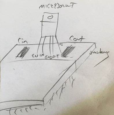
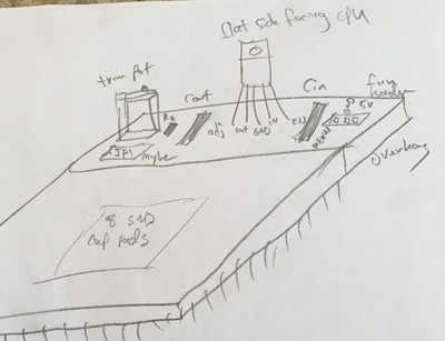
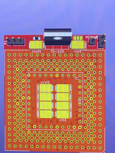
It is my opinion that the tach via be removed. You can still plug in a 3-wire fan cable to a 2-pin header. It will not hinder operation at all. You could even include one of those white fan connectors if you so choose, just remove the 3rd pin from it. I think we can let the individual doing the layout make up his own mind at this point.

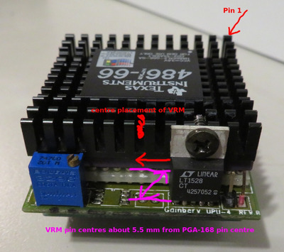
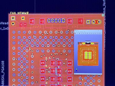
From the majority of 386/486 interposers I've seen, they try to keep at least Cin next to the VRM. So I'm wondering if JP1 and tach vias removed, is there space to place Cin next to the VRM? Or if a 2-pin fan and MEMW# are placed on the same header, can 1x Cout and 1x Cin fit near the VRM? If not, what if their form factor is reduced, as discussed earlier?

Plan your life wisely, you'll be dead before you know it.

Reply 261 of 1228, by feipoa

User metadata
Rank l33t++
Rank
l33t++

I remember thinking about this J1 issue in the past for some time. The call-out and wording in the SXL databook doesn't make sense to me. Let me review my notes first. I don't understand why they are writing Vcc/Vcc5* If using a 5V CPU, wouldn't this pin would already be set to 5V, if using a 3.6 V CPU, the motherboard would already be set to 3.6V. I previously determined that this pin should always be 5V, but I'm second guessing myself now.

Plan your life wisely, you'll be dead before you know it.

Reply 262 of 1228, by Sphere478

User metadata
Rank l33t++
Rank
l33t++

With the power planes I am designing for you, we can put those caps wherever we want 😀 entire layers are conducting the power, all we gotta do is send a few vias down to the layer we need. But if you specifically want caps in a specific place, draw me a sketch of what you are thinking? 😀

How about a compromise on the hole as it seems like more than one person will use this, I can delete the silk outline of the 3 pin header and replace it with only a two pin outline. But still have a hole and proper clearance should someone decide to use a three pin. It should look very period correct with only two pins installed.

Vcc generic term for positive voltage unspecified

Vss generic term for neutral/ground/0v

Vcc3 3v
Vcc5 5v
Vcc2 2v

Sphere's PCB projects.
-
Sphere’s socket 5/7 cpu collection.
-
SUCCESSFUL K6-2+ to K6-3+ Full Cache Enable Mod
-
Tyan S1564S to S1564D single to dual processor conversion (also s1563 and s1562)

Reply 263 of 1228, by feipoa

User metadata
Rank l33t++
Rank
l33t++

I am going to see what the Evergreen unit does with the J1 Vcc/VCC5 pin. It may even be is left floating, but I will confirm. If you look at the datasheet, even for the QFP144 variant, which I thought was 3.45/3.6V only, it also is ambiguous about J1.

There have been perhaps a dozen individuals who have expressed interest in this adapter thus far. If/when it actually exists, I expect this number to increase.

Seems to me that, from the onset, one would just order an appropriated sized fan without the tach. If I end up assembling several of these units, adding components, fans, etc, I'd be ordering fans without the tach. Just my personal opinion here, but I find it kinda tacky using a fan with a tach when it cannot be read by anything. Pretty much all my smaller fans doesn't have a tach.

I've attached an image for caps Cin and Cout. Is there space for them to fit on the overhang as shown? Perhaps leave the buried cap locations as is.

cap_placement.JPG
Filename
cap_placement.JPG
File size
121.21 KiB
Views
671 views
File license
CC-BY-4.0

Plan your life wisely, you'll be dead before you know it.

Reply 264 of 1228, by Sphere478

User metadata
Rank l33t++
Rank
l33t++

Yeah, I can do that. You want the caps in center to stay there also you are saying? (You could always leave them unpopulated)

Where do you want the other parts?

Sphere's PCB projects.
-
Sphere’s socket 5/7 cpu collection.
-
SUCCESSFUL K6-2+ to K6-3+ Full Cache Enable Mod
-
Tyan S1564S to S1564D single to dual processor conversion (also s1563 and s1562)

Reply 265 of 1228, by feipoa

User metadata
Rank l33t++
Rank
l33t++

Can those large caps fit in the orientation I placed them in? If so, then the trimmer can stay put. The SMD resistor would be best placed next to the trimmer. JP1 might have to go - let me figure out the issue with the J1 PGA pin first. The fan header can stay at the other end, but might need to be amalgamated with MEMW# for space. The VRM, may be OK, but I was wondering if it should be rotated 180 degrees so that the contact pad can be affixed to the heatsink, like was done on these Gainbery modules? download/file.php?id=145117&mode=view If that's the case, then the other components should be flipped to the other side of the overhang.

Plan your life wisely, you'll be dead before you know it.

Reply 266 of 1228, by Sphere478

User metadata
Rank l33t++
Rank
l33t++

Turning them like that will make the protrusion wider than I have it now but I can turn them like that.

Sphere's PCB projects.
-
Sphere’s socket 5/7 cpu collection.
-
SUCCESSFUL K6-2+ to K6-3+ Full Cache Enable Mod
-
Tyan S1564S to S1564D single to dual processor conversion (also s1563 and s1562)

Reply 267 of 1228, by feipoa

User metadata
Rank l33t++
Rank
l33t++

Here's another image. I don't think we'd want to make the overhang any larger. So perhaps either rotate the caps around, or using the smaller 1206 size noted on page 13?

Attachments

Plan your life wisely, you'll be dead before you know it.

Reply 268 of 1228, by Sphere478

User metadata
Rank l33t++
Rank
l33t++

Okay. Just so you know though, there isn’t really a need to have the caps over there if they are in the center already.

I’ll throw that design together so you can take a peek.

Sphere's PCB projects.
-
Sphere’s socket 5/7 cpu collection.
-
SUCCESSFUL K6-2+ to K6-3+ Full Cache Enable Mod
-
Tyan S1564S to S1564D single to dual processor conversion (also s1563 and s1562)

Reply 269 of 1228, by Sphere478

User metadata
Rank l33t++
Rank
l33t++
feipoa wrote on 2022-09-13, 21:18:

Here's another image. I don't think we'd want to make the overhang any larger. So perhaps either rotate the caps around, or using the smaller 1206 size noted on page 13?

image.jpg
Filename
image.jpg
File size
1.87 MiB
Views
609 views
File license
Public domain

I assembled as you suggested and then did a little re sorting to make things fit better. Thoughts on this modification of your suggestion?

I broke up your 3 pin header to avoid tach being plugged into memw# by accident by future user.

Remember the left header is your trim pot. Does clearance look okay on it?

Btw, in general more caps the better but if we get too many there will be a large inrush current on power up. Depending on the value you plan to use this may or may not be significant. Recommend you use a weak psu for testing and populate all locations to see if problem presents. Removal of some will likely fix the issue if it occurs.

As a reminder, there is still a lot of work left to do on the signal routing. So it’s still going to be a while before prototype. But I think we need to nail down the layout before I go much further.

Are you sure there are no additional switches you want? Check my socket 3 tweaker thread for ideas. With a little creativity I think I can still add back the three pin fan header to satisfy other users without making a larger overhang. Overhang is the same size as last render still.

Edit: flipped reg. You want tab toward cpu? Does reg heatsink fit better this way?

Sphere's PCB projects.
-
Sphere’s socket 5/7 cpu collection.
-
SUCCESSFUL K6-2+ to K6-3+ Full Cache Enable Mod
-
Tyan S1564S to S1564D single to dual processor conversion (also s1563 and s1562)

Reply 270 of 1228, by feipoa

User metadata
Rank l33t++
Rank
l33t++

We should be fine to break-out MEMW# from the fan header, space permitting.

Regarding clearance on the trim pot, it measures 5.0 mm deep by 9.5 mm wide. I've attached a photo showing the dimensions. The wording on the trim pot and the VRM should be facing outwards, just like in the photos below. The pins to use on the trim pot should be pins 1 & 2, making up R1. Pin 3 should be connected to Pin 2 with a trace. See photo.

Trim_pot_1K_ connection.JPG
Filename
Trim_pot_1K_ connection.JPG
File size
69.98 KiB
Views
597 views
File license
CC-BY-4.0

With respect to the VRM - I was not planning on adding a heatsink to it directly, but instead, affixing it to the SXL2-66's heatsink (if necessary), like Gainbery did with the IBM 5x86c upgrades. See photo. For this to work, we'd want to ensure that the VRM is centred to the PGA-168's centre. It was difficult to measure, but it looks like the distance from the VRM's pin centre to the first PGA-168's pin centre is 5.5 mm.

Since we want to centre the VRM's tab to that of the factory heatsink, we are limited to two possible orientations for the PGA-168 socket. One suitable orientation is shown in the attached photo. Another suitable orientation is having the PGA-168 orientation flipped 180 degrees from that shown in the photo. I suppose you'd want to pick which either of these two orientations yields the shortest average trace lengths.

VRM_orientation.JPG
Filename
VRM_orientation.JPG
File size
222.69 KiB
Views
597 views
File license
CC-BY-4.0

Lastly, I looked into VCC5 a bit further. On my PGA-168 SXL-40 and SXL2-50, VCC5 is connected to VCC, because the chip is already running at 5V to begin with. On the SXL2-66, 3.6V, which is the chip we are using (photo), VCC5 is not connected to VCC. In looking at the Evergreen SXL2-66 QFP144, I found that VCC5, aka PGA168 pin J1, is connected to 5V rather than Vcc (3.6V). My guess is that TI always wants 5V for on J1 for the use of MEMW#. Therefore, we should be eliminating the JP1 solder pads in the design. VCC5 (J1) should always be wired directly to 5V and would never be run at 3.x volts.

Last edited by feipoa on 2022-09-14, 19:50. Edited 1 time in total.

Plan your life wisely, you'll be dead before you know it.

Reply 271 of 1228, by H3nrik V!

User metadata
Rank Oldbie
Rank
Oldbie
feipoa wrote on 2022-09-14, 09:06:

With respect to the VRM - I was not planning on adding a heatsink to it directly, but instead, affixing it to the SXL2-66's heatsink (if necessary), like Gainbery did with the IBM 5x86c upgrades. See photo. For this to work, we'd want to ensure that the VRM is centred to the PGA-168's centre. It was difficult to measure, but it looks like the distance from the VRM's pin centre to the first PGA-168's pin centre is 5.5 mm.

Voltage or polarity of the cooling tab of the VRM should be considered in this case ...

Please use the "quote" option if asking questions to what I write - it will really up the chances of me noticing 😀

Reply 272 of 1228, by Sphere478

User metadata
Rank l33t++
Rank
l33t++

Yeah, those cooling/center tabs are sometimes live.

We may be energizing the processor heatsink. Which is what may happen to a clip on heatsink also of course. Moral of the story, don’t let tab or things touching tab touch metal stuff

Okay if we are aiming for a specific spot left vs right and forward vs back then we need some very precise measurements for where the center of the holes should be located. I’ll go off your pic and make a new draft

Sphere's PCB projects.
-
Sphere’s socket 5/7 cpu collection.
-
SUCCESSFUL K6-2+ to K6-3+ Full Cache Enable Mod
-
Tyan S1564S to S1564D single to dual processor conversion (also s1563 and s1562)

Reply 273 of 1228, by feipoa

User metadata
Rank l33t++
Rank
l33t++

The tab on the VRM is GND - I've checked already with an exact model in hand. The flow from an affixed fan on the heatsink can cool the VRM in the manner drawn above. Adding a second heatsink takes extra space and is unnecessary.

Plan your life wisely, you'll be dead before you know it.

Reply 275 of 1228, by Sphere478

User metadata
Rank l33t++
Rank
l33t++

I’m in favor of a three pin fan header if it will fit, but it’s not the end of the world to not have it.

I like how a three pin plug will hold more firm to the header than a simple two pin will and the fact that most of us have drawers full of three pin fans already.

Those wanting to use a two pin need only solder in a two pin header. It will look just like a two pin header. Why we have to remove compatability with three pin headers seems silly when we can set up the board for both.

Anyway, not the end of the world to use a two pin header footprint and not worth fighting over so it seems we will only have two pins from here forward unless there is a movement to bring it back. I don’t really have a horse in this race as I won’t be ordering one for myself as I don’t have these chips.

Anyway glad to hear that the tab is ground, that is handy.

I should be able to make some adjustments tonight and upload another image for your perusal.

Are we sure we don’t want to make it impossible for memw to be plugged into a 3 pin fan? That is a super easy mistake to make… why wouldn’t we move it slightly to keep people from plugging a 3 pin fan into it?

If that’s what you want though, so it shal be.

Sphere's PCB projects.
-
Sphere’s socket 5/7 cpu collection.
-
SUCCESSFUL K6-2+ to K6-3+ Full Cache Enable Mod
-
Tyan S1564S to S1564D single to dual processor conversion (also s1563 and s1562)

Reply 276 of 1228, by feipoa

User metadata
Rank l33t++
Rank
l33t++

You have a drawer full of fans for a 486-sized processor with a tach? For my fan bins, almost all 486 and smaller don't have the yellow wire. However, even if you have extras with the tach, the yellow wire can be snipped off or desoldered if necessary.

As for not having the processors, I should have a dozen or so on hold for me. I'll check with my source.

Yes, we can have MEMW# not part of the fan header. I wrote as such in my previous message.

feipoa wrote on 2022-09-14, 09:06:

We should be fine to break-out MEMW# from the fan header, space permitting.

With "break-out" I mean it can be removed from the 3-pin header and have its own header.

What we definitely want to get rid of is JP1. VCC5 should always be 5 V, regardless of the version of SXL CPU used. I can see people confusing JP1 for bypassing the VRM, which it does not do.

Plan your life wisely, you'll be dead before you know it.

Reply 277 of 1228, by Sphere478

User metadata
Rank l33t++
Rank
l33t++

Okay. I’ll try and work on this some more tonight. 😀

I misunderstood you about the memw# pin. Right on. All good then.

Sphere's PCB projects.
-
Sphere’s socket 5/7 cpu collection.
-
SUCCESSFUL K6-2+ to K6-3+ Full Cache Enable Mod
-
Tyan S1564S to S1564D single to dual processor conversion (also s1563 and s1562)

Reply 278 of 1228, by Sphere478

User metadata
Rank l33t++
Rank
l33t++

Got the fet located.

image.jpg
Filename
image.jpg
File size
1.93 MiB
Views
512 views
File license
Public domain

Got rid of the solder bridge

re arranged parts

extended flood planes.

Added trace for trim pot bridge.

Pulled in the overhang a tiny bit. 😀

How’s this look?

According to the footprints we have a slight overlap on the courtyard between the large socket and the fet. If you want to triple check that measurement. (Center pin of large socket to center pin of fet.

Attachments

  • image.jpg
    Filename
    image.jpg
    File size
    1.37 MiB
    Views
    504 views
    File license
    Public domain

Sphere's PCB projects.
-
Sphere’s socket 5/7 cpu collection.
-
SUCCESSFUL K6-2+ to K6-3+ Full Cache Enable Mod
-
Tyan S1564S to S1564D single to dual processor conversion (also s1563 and s1562)

Reply 279 of 1228, by feipoa

User metadata
Rank l33t++
Rank
l33t++

Looking really slick. yes, I was planning on finding a way to get a more precise measurement either this evening or the next.

EDIT: How much of an overlap does it say there is?

Plan your life wisely, you'll be dead before you know it.