VOGONS


The 286 Laptop Restoration Thread

Topic actions

Reply 80 of 87, by miclass

User metadata
Rank Newbie
Rank
Newbie

Ciao all - small update from here - I spent a lot of time testing continuity of all traces around the Boost 12V components, luckly everything seems fine for my tester (I admit I would have prefered finding something wrong...at least I would have found a problem...).

I had already dissoldered Q2, Q3, Q4, Q21, Q22, Q23 and checked them with the components tester and they also seem good. Same for L3 and diode 12. I decided to dissolder also UPA1600 and test each ones of its mosfet singularly,...they also seem all fine, both for the component tester and I also did a try generating a PWM at 70khz from arduino, it seemed to switch properly (I will try the same also with Q2, Q3 and Q4...).

I am quite clueless in this moment, I have ordered a new UPA1600 just because I have found it on aliex for few € and mine seems a little bit"baked" (it has lost the tag on it)...even if it seems working. When I will receive the UPA1600, I will try to reassemble all components and test again,...hopefully with my cheap oscilloscope I will get some hint before seeing again some white smoke... 😀 Hope to have some good news soon!

Here some pics from the board and some particular parts:
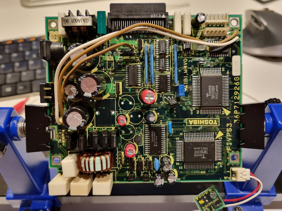
board-front.jpg
PSU upside, some components missing...I tried to clean it as much as possible with isopropilic alcool
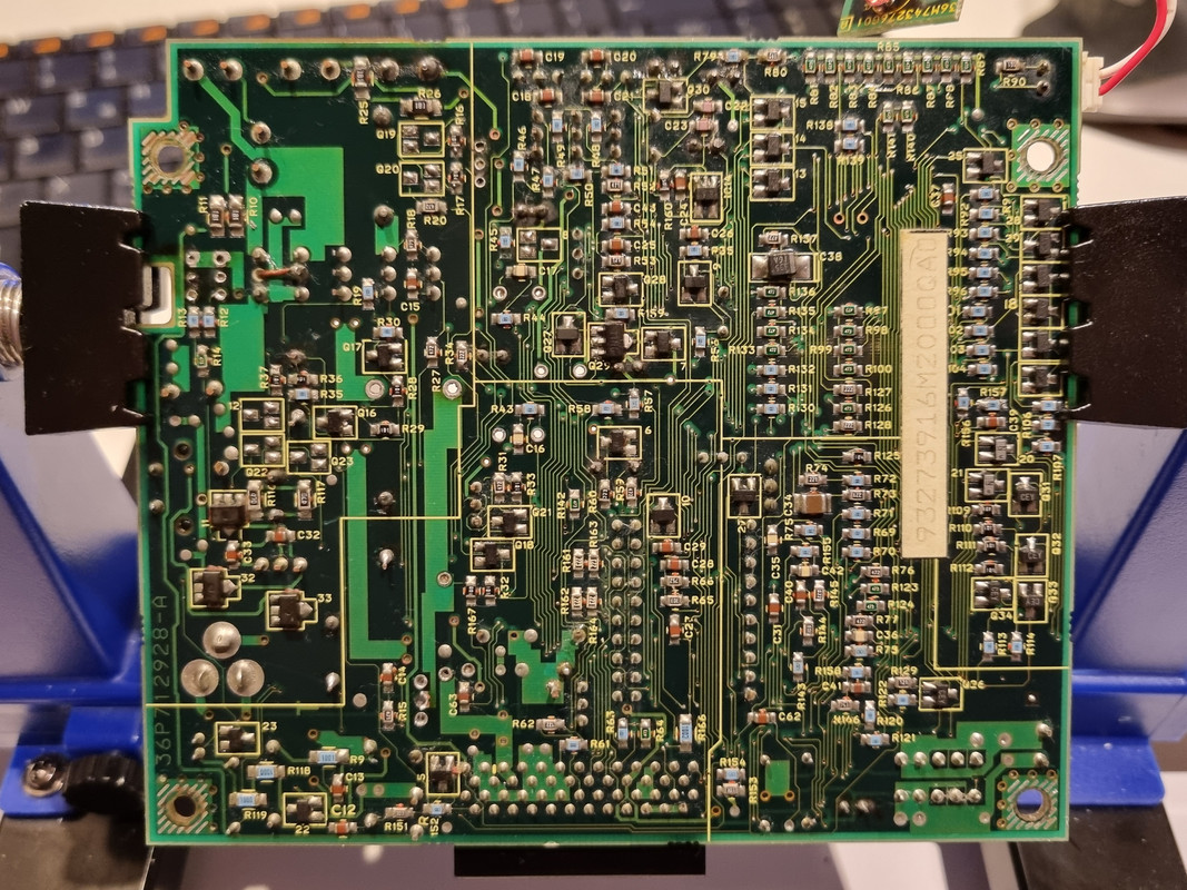
board-back.jpg
PSU backside...here I had to change Q29...
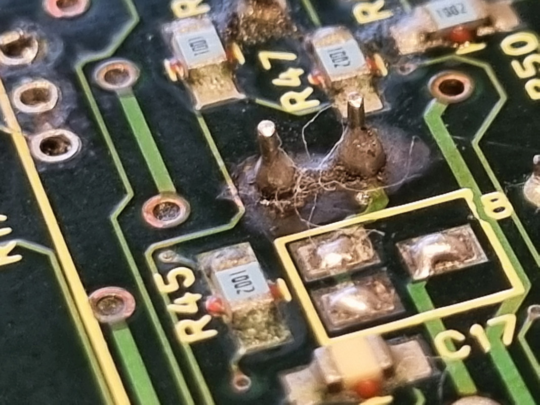
C4-mess-small.jpg
C4 after replacement...this was really a mess, C4 and C7 really leaked a lot and corrosion was important, remove them was a pain... The trace on the left seems damage but for the tester is Ok...
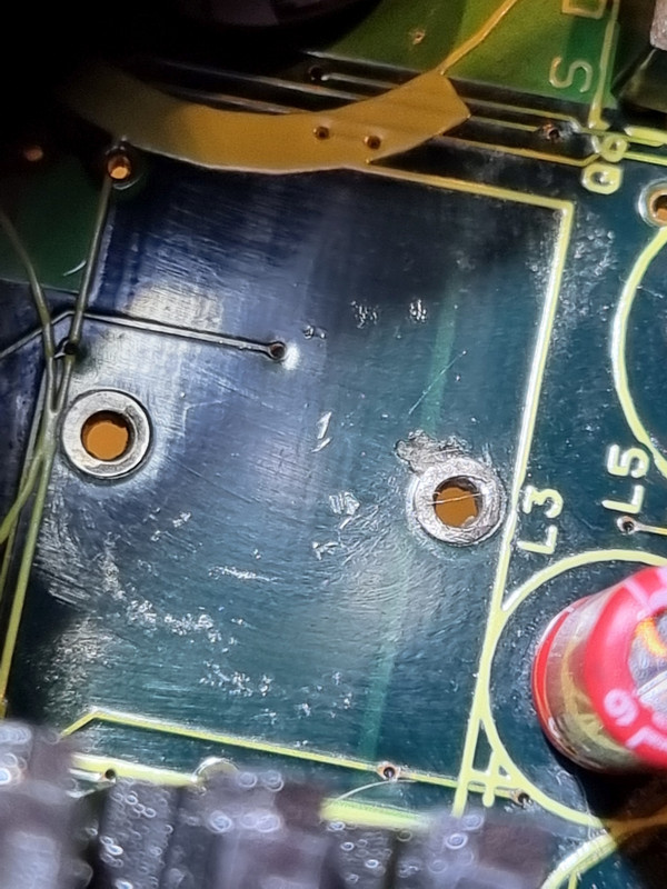
L3-problem-small.jpg
L3 place...here there is something strange on the right hole, I does measure as a short but it does not look so good...again there was some corrosion here...
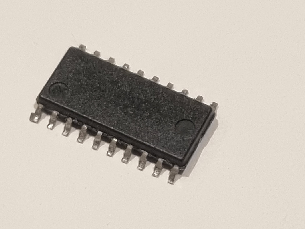
UPA1600-backed-small.jpg
UPA1600 - it lost the tag on it while cleaning...I don't know if due to overheat or what...

Reply 81 of 87, by FuST

User metadata
Rank Newbie
Rank
Newbie

That looks like a lot of corrosion on the solder joints.
I'd say the uPA1600's are probably fine (they can take quite some abuse) and the problem is more likely to be a damaged trace somewhere.

First things first though: check if all totempole driver combinations see a PWM signal. You'll need to use single trigger mode on your 'scope for that.
Next check if all the switchmode converters actually switch. I.e. check the output voltages using a 'scope in single trigger mode.

That way you can isolate the problem to a single converter/rail and work from there.
It's all about confirming what does work, crossing it off (I literally cross it off in the schematic) and checking whatever is left in the end. Tedious but doable.

Blog | YouTube

Reply 82 of 87, by perezx

User metadata
Rank Newbie
Rank
Newbie

Hey guys, again!
I was missing for some time and the laptop got covered by dust. Finally my friend agreed to have a look at it and he found that Q29 was one of the problems - at 1V Drain-Source voltage it worked like everything okay, but at 2V Ids = 2A, so some kind of avalanche breakdown.
When Q29 was replaced, the PSU reached stable +18V on primary circuit.... but NO PWM on any other converter. It even does not try to start them up. WTH? Any Ideas?

Reply 83 of 87, by FuST

User metadata
Rank Newbie
Rank
Newbie
perezx wrote on 2024-05-29, 14:32:

When Q29 was replaced, the PSU reached stable +18V on primary circuit.... but NO PWM on any other converter. It even does not try to start them up. WTH? Any Ideas?

Are you saying the +18V internal rail comes up and stays up (I.e. the microprocessor keeps generating PWM for it indefinitely) while the other converters are completely dead?
That doesn't make any sense to me. If the microprocessor senses a fault it should shut down everything immediatly, including the +18V internal converter.

Blog | YouTube

Reply 84 of 87, by miclass

User metadata
Rank Newbie
Rank
Newbie
FuST wrote on 2024-05-22, 06:03:
That looks like a lot of corrosion on the solder joints. I'd say the uPA1600's are probably fine (they can take quite some abuse […]
Show full quote

That looks like a lot of corrosion on the solder joints.
I'd say the uPA1600's are probably fine (they can take quite some abuse) and the problem is more likely to be a damaged trace somewhere.

First things first though: check if all totempole driver combinations see a PWM signal. You'll need to use single trigger mode on your 'scope for that.
Next check if all the switchmode converters actually switch. I.e. check the output voltages using a 'scope in single trigger mode.

That way you can isolate the problem to a single converter/rail and work from there.
It's all about confirming what does work, crossing it off (I literally cross it off in the schematic) and checking whatever is left in the end. Tedious but doable.

I received the UPA1600 and I substituted it, even if as you are saying most probably it was working. Then I proceed to mount again all components I dissoldered in the meantime (Q19, Q20, Q22, Q23, Diode 8, Diode 12, Q2, Q3, Q4 and Q5)...all these componentes were fine according to my components testers. I checked again all connections to verify continuity and everything was good.

I connect the power supply with a bit of hope...but I got:

- immediately red led blinking, Q2 and Q3 very hot (there was some residual solder paste that smoked immediately)...I disconnected and then I tried to connect it again for very few seconds to just get some measure...but...
- Q2 and Q3 stooped to be hot (broken again?) and Q5 started to smoke...again I disconnected and connected again for very few seconds...something getting also a solid red led, sometimes also the led soldered on IC2 turned led without switching it on... then Q5 stopped to smoke, and Q2/Q3 started again....then...both seemed fine for few seconds (all led solid)...and
- Q14 created a lot of quite smoke...(I think it's broken now...)...and I disconnected everything...

Now I am very frustrated by this situation...I spent a lot of timing dissoldering/soldering again and testing components but I am not able to point out the problem, the board had a very erratic behaviour, seems different everytime I connect it to power, and I am really clueless in what to do next 🙁

i don't want to abandon this recovery project but it seems really an hard problem. Do you have any suggestion?

Thank you.
-miclass

Reply 85 of 87, by perezx

User metadata
Rank Newbie
Rank
Newbie
FuST wrote on 2024-06-07, 18:38:
perezx wrote on 2024-05-29, 14:32:

When Q29 was replaced, the PSU reached stable +18V on primary circuit.... but NO PWM on any other converter. It even does not try to start them up. WTH? Any Ideas?

Are you saying the +18V internal rail comes up and stays up (I.e. the microprocessor keeps generating PWM for it indefinitely) while the other converters are completely dead?
That doesn't make any sense to me. If the microprocessor senses a fault it should shut down everything immediatly, including the +18V internal converter.

Hi again, nice to meet you 😀
Sure, +18 rail shuts down soon (possibly when its time to power up other rails). I do not see what kind of error IC13 finds assuming that +18 is okay now and no other converter starts...

Reply 86 of 87, by miclass

User metadata
Rank Newbie
Rank
Newbie

Another update on my PSU, after the dramatic failure of some days ago I dissoldered some of the components that I saw smoking or becoming very hot, and I found:

Q14 to be broken apart, cracked between source/drain
Q29 KO
Q2 / Q3 still OK, according to my components tester
Q5 KO
Q6 KO

Then:
- what could cause such a catastrofic failure with components failing one after the other? I am doing a lot of testing on continuity to find out broken traces or shorts but no luck so far...
- how to proceed now? I have order spare parts to substitute these components but I think that if I reassemble everything and switch it on I will get the same result... could be an idea to proceed with an order and add one mosfet per time and check, avoiding to fry again everything?

Thanks!
-miclass

Reply 87 of 87, by FuST

User metadata
Rank Newbie
Rank
Newbie
perezx wrote on 2024-06-10, 08:30:

Sure, +18 rail shuts down soon (possibly when its time to power up other rails). I do not see what kind of error IC13 finds assuming that +18 is okay now and no other converter starts...

That is in line with what I would expect.
First things first: make sure you're waiting about 10-20 seconds in between tries when powering up the board as IC13 needs to be powered down completely for a second or two to fully reset it.
Next check the PWM in- and outputs of the UPA1600 buffers (IC5 & IC11). There should be a PWM signal there, even for a short while. Make sure you're using an oscilloscope capable of such short pulses and use single-shot mode to try to capture it.

miclass wrote on 2024-06-12, 12:30:

- what could cause such a catastrofic failure with components failing one after the other? I am doing a lot of testing on continuity to find out broken traces or shorts but no luck so far...
- how to proceed now? I have order spare parts to substitute these components but I think that if I reassemble everything and switch it on I will get the same result... could be an idea to proceed with an order and add one mosfet per time and check, avoiding to fry again everything?

There must be a short somewhere but it might be caused by something that's not so obvious.
In any case: stop applying power to the board when components get hot or start to smoke, the chances of causing a lot more damage that way are very high.
One thing that immediately springs to mind when reading the list of destroyed components is that the MOSFETs are constantly conducting, be it partially or completely *.

I'd check that the resistors responsible for pulling up the totem-pole drivers are within spec and are connected to the appropriate rails (+18V and V+ main, depending on the rail IIRC). Next check that the totem-pole transistors are good.
After that I'd backtrack the PWM signals like I described above in my reply to perezx.

EDIT: Forgot to add that you might be able to populate just one MOSFET at the time to test things out one at the time. Don't just take my word for it though, check the schematic and maybe simulate parts if you're unsure. Removing the wrong components (ex: pull-up resistors) can result in something just shorting to ground and frying things more.
They might pop again because the problem lies elsewhere (like the driving circuitry for example) which is one of the reasons I always advise to buy one or two more than you need.
And lastly: don't just throw parts at a problem without verifying it actually is problematic. That is a very expensive and frustrating way to troubleshoot things.

*: MOSFETs need to be driven to fully open/closed very fast, they have high resistance causing heating in the in-between region

Blog | YouTube