VOGONS


Asus K7V Slot A hi-lo-hi-lo beeps

Topic actions

Reply 20 of 36, by butjer1010

User metadata
Rank Member
Rank
Member
rasz_pl wrote on 2024-04-20, 19:57:
Average would actually help a lot when measuring in circuit. Bit its not average. Its 1/R = 1/R1 + 1/R2 +1/R3 + ... Measuring in […]
Show full quote
momaka wrote on 2024-04-20, 15:26:

The problem with checking caps on board is that if you have two or more connected in parallel (often the case on CPU V_core rail ,but not only) the meter will show the average ESR for all of the parallel caps... so you'll never know if one of them (or all of them) are bad, unless absolutely all of them are terribly terribly bad (near open-circuit for each cap.)

Average would actually help a lot when measuring in circuit. Bit its not average.
Its 1/R = 1/R1 + 1/R2 +1/R3 + ...
Measuring in circuit is still valid because parallel caps are usually of same make and model and fail together.

-----------------

More advanced boards around 2000 started incorporating mechanisms to signal error/prevent boot before CPU starts running.
butjer1010 have you tried starting the board with no CPU at all? Its possible you will hear same alarm, in that case problem is with either
-FAN detection
-CPU
-CPU power circuit
-some other voltage rail on board
In any of those cases POST card will show nothing.

Hi, i tried without CPU, and there is no beeps at all.....

Reply 21 of 36, by rasz_pl

User metadata
Rank l33t
Rank
l33t

Ok, so at least now we know its the BIOS doing the beeps and CPU is running. How about only CPU and nothing else plugged? no ram no keyboard nothing, just mobo cpu speaker and supply.

Open Source AT&T Globalyst/NCR/FIC 486-GAC-2 proprietary Cache Module reproduction

Reply 22 of 36, by butjer1010

User metadata
Rank Member
Rank
Member
rasz_pl wrote on 2024-04-20, 23:14:

Ok, so at least now we know its the BIOS doing the beeps and CPU is running. How about only CPU and nothing else plugged? no ram no keyboard nothing, just mobo cpu speaker and supply.

Siren again 🙁
So it doesn't go to the ram in the POST, it stops at CPU?

Reply 23 of 36, by zuldan

User metadata
Rank Member
Rank
Member
butjer1010 wrote on 2024-04-21, 09:25:
rasz_pl wrote on 2024-04-20, 23:14:

Ok, so at least now we know its the BIOS doing the beeps and CPU is running. How about only CPU and nothing else plugged? no ram no keyboard nothing, just mobo cpu speaker and supply.

Siren again 🙁
So it doesn't go to the ram in the POST, it stops at CPU?

Silly question, do you know the CPU’s you are using are 100% working?

Have you tried powering on the board without the CR2032 battery?

Reply 24 of 36, by butjer1010

User metadata
Rank Member
Rank
Member
zuldan wrote on 2024-04-21, 09:40:
butjer1010 wrote on 2024-04-21, 09:25:
rasz_pl wrote on 2024-04-20, 23:14:

Ok, so at least now we know its the BIOS doing the beeps and CPU is running. How about only CPU and nothing else plugged? no ram no keyboard nothing, just mobo cpu speaker and supply.

Siren again 🙁
So it doesn't go to the ram in the POST, it stops at CPU?

Silly question, do you know the CPU’s you are using are 100% working?

Have you tried powering on the board without the CR2032 battery?

I have 2 Athlons, one 600, other 650MHz, i doubt both of them are faulty. On monday or tuesday i will receive another Slot A motherboard, and i will try all the CPUs on this working board. Then i will be 100% sure they are ok.
Yes, i removed the battery for all night, and try to turn on without today, but no difference....

Reply 25 of 36, by momaka

User metadata
Rank Member
Rank
Member
butjer1010 wrote on 2024-04-21, 09:25:

So it doesn't go to the ram in the POST, it stops at CPU?

Typically before board checks for RAM, first POST checks that all power rails are up and running. Then CPU is initialized, then RAM (IIRC.)

So it could still be a power issue, a CPU detection issue, or fan detection issue.
Some socket A boards in particular are known to not initialize if they can't read fan RPM. This is because socket A CPUs **WILL** burn out instantly if there is no heatsink installed on them. I suppose the idea behind this mechanism was so that if someone wanted to test a board hastily without installing the CPU cooler, the board would prevent the CPU from burning in that case.
Now, I don't know if this safety mechanism was invented earlier and perhaps on Slot A boards too. But in any case, make sure your CPU fan header gets a 3-pin fan that can be properly read for RPM on motherboards. Also check around the fan header for any missing or chipped components or broken / scratched traces. In fact, do that inspection on the entire board.

rasz_pl wrote on 2024-04-20, 19:57:

Average would actually help a lot when measuring in circuit. Bit its not average.
Its 1/R = 1/R1 + 1/R2 +1/R3 + ...

Right.
What I meant by average is the equivalent ESR of all the parallel caps.
Just didn't want to get technical with formulas for the sake of brevity. 😉

rasz_pl wrote on 2024-04-20, 19:57:

Measuring in circuit is still valid because parallel caps are usually of same make and model and fail together.

Not always the case.
I've seen it one too many times when only a handful of caps failed and the rest were OK and never gave problems.

And here is an example why measuring caps still on the board isn't a good idea:
Let's say a board has 5 caps with 20 mOhms nominal ESR / impedance. The parallel impedance of all these would be 4 mOhms.
But what happens if only one cap goes bad and completely O/C (infinite impedance)?
The equivalent impedance goes up to 5 mOhms.
Given the tolerance of most ESR meters, you would not be able to catch this at all.
Now if 3 of the 5 caps fail, then the impedance increases to 10 mOhms... which if you have a really really really well calibrated ESR meter, it just *might* raise some suspicion. But even then, it wouldn't be too hard to dismiss it as if everything is OK. Perhaps if you go check the capacitance and notice that now the total capacitance has fallen drastically due to 3 of the 5 caps being completely O/C. Realistically, however, most bad caps don't fail open-circuit (save for Sacon FZ). Often their impedance will go up 100-1000x. What's more interesting is that some failed caps will read an abnormally high capacitance due to high internal leakage current. Actually, these usually show good ESR too, since the high internal leakage often tricks ESR meters too. The result is that you might get a perfect reading ESR and capacitance wise, and still have failed caps in there. Some of the worst offenders to this would be Nichicon HM, HN, and HZ series manufactured between 2001 and 2004 (H01xx through H04xx date codes, where xx = number of the week the caps were manufactured.) In their early stage of failure, these often don't bulge or leak. Yet they can still be bad. I recapped a crashing Intel P4 mobo of mine a few years back like this. It all looked fine on the surface... but as soon as I saw the 6.3V 2200 uF Nichicon HM caps on the CPU VRM, I immediately suspected them and pulled them out. Unsurprisingly, two of them were failed with abnormally high capacitance (almost 2x) and still showed perfectly low ESR (due to tricking my meter with the high leakage current.) Replacing them fixed the crashing issue.

The above is not a 1-off issue. I've seen it many times on other people's boards too.

So I stand by my argument that caps cannot be checked in-circuit, at least when there are multiple of them in parallel.
Now if you know and understand the circuit you are checking very well, then you may be able to check it with the caps still in it.
Reply 26 of 36, by butjer1010

User metadata
Rank Member
Rank
Member
momaka wrote on 2024-04-21, 17:22:
Typically before board checks for RAM, first POST checks that all power rails are up and running. Then CPU is initialized, then […]
Show full quote
butjer1010 wrote on 2024-04-21, 09:25:

So it doesn't go to the ram in the POST, it stops at CPU?

Typically before board checks for RAM, first POST checks that all power rails are up and running. Then CPU is initialized, then RAM (IIRC.)

So it could still be a power issue, a CPU detection issue, or fan detection issue.
Some socket A boards in particular are known to not initialize if they can't read fan RPM. This is because socket A CPUs **WILL** burn out instantly if there is no heatsink installed on them. I suppose the idea behind this mechanism was so that if someone wanted to test a board hastily without installing the CPU cooler, the board would prevent the CPU from burning in that case.
Now, I don't know if this safety mechanism was invented earlier and perhaps on Slot A boards too. But in any case, make sure your CPU fan header gets a 3-pin fan that can be properly read for RPM on motherboards. Also check around the fan header for any missing or chipped components or broken / scratched traces. In fact, do that inspection on the entire board.

I have 3pin fan connected, even tried few of them. I will try to find any damage near the fan connector.
Thanks

Reply 27 of 36, by rasz_pl

User metadata
Rank l33t
Rank
l33t

I do have schematic for K7V, sadly its bad quality paper one scanned long time ago, no ocr and low readability 🙁

Filename
ASUS K7V.7z
File size
4.41 MiB
Downloads
5 downloads
File license
Fair use/fair dealing exception

Asus liked to do "ASICs" on their board for things like power/fan/temp monitoring, and this board is no different. Suspects are:

1. "AS61256-8" mentioned by me some time ago in reference to P5A Re: Asus P5A Missing Components
Sadly its one of ASUS ASICs I have no documentation for, but we do have pinouts in this diagram and P5A boardview and different revision P5A uses bunch of TTL in its place so its just a dump buffer with no advanced logic inside.

2. Main monitoring chip AS98127F (page 24). I do have AS99127F documentation 😀

Filename
As99127f.pdf
File size
772.41 KiB
Downloads
5 downloads
File license
Fair use/fair dealing exception

Now reading the description its not entirely clear to me yet if this chip is capable of performing monitoring/alarm functions on boot without being programmed by the BIOS. PDF gives the impression that it needs to be initialized by CPU, on the other hand such chip should be able to do stand alone cutoff to protect system before starting.

This chip does indeed have an ALARM BEEPER function where it will sound the on of on of 50% duty cycle siren if it doesnt like something.
" So, the beeper will beep-stop-beep-stop"
Pin 77 HMBEEP going to page 20 transistor Q42 right into speaker.

butjer1010 get a multimeter and carefully (dont short anything, pins are very small) using very sharp probe measure (DC voltage mode, 5V range) all the pins of this chip according to attached doc while turned on and beeping. We are interested in all
-INx
-Analog Input
pins (pages 4-7).

Open Source AT&T Globalyst/NCR/FIC 486-GAC-2 proprietary Cache Module reproduction

Reply 28 of 36, by butjer1010

User metadata
Rank Member
Rank
Member
rasz_pl wrote on 2024-04-21, 20:38:
I do have schematic for K7V, sadly its bad quality paper one scanned long time ago, no ocr and low readability :( ASUS K7V.7z […]
Show full quote

I do have schematic for K7V, sadly its bad quality paper one scanned long time ago, no ocr and low readability 🙁
ASUS K7V.7z

Asus liked to do "ASICs" on their board for things like power/fan/temp monitoring, and this board is no different. Suspects are:

1. "AS61256-8" mentioned by me some time ago in reference to P5A Re: Asus P5A Missing Components
Sadly its one of ASUS ASICs I have no documentation for, but we do have pinouts in this diagram and P5A boardview and different revision P5A uses bunch of TTL in its place so its just a dump buffer with no advanced logic inside.

2. Main monitoring chip AS98127F (page 24). I do have AS99127F documentation 😀 As99127f.pdf
Now reading the description its not entirely clear to me yet if this chip is capable of performing monitoring/alarm functions on boot without being programmed by the BIOS. PDF gives the impression that it needs to be initialized by CPU, on the other hand such chip should be able to do stand alone cutoff to protect system before starting.

This chip does indeed have an ALARM BEEPER function where it will sound the on of on of 50% duty cycle siren if it doesnt like something.
" So, the beeper will beep-stop-beep-stop"
Pin 77 HMBEEP going to page 20 transistor Q42 right into speaker.

butjer1010 get a multimeter and carefully (dont short anything, pins are very small) using very sharp probe measure (DC voltage mode, 5V range) all the pins of this chip according to attached doc while turned on and beeping. We are interested in all
-INx
-Analog Input
pins (pages 4-7).

Uffff,
i need 2 days just to read all this 😀
When i read all, i will try to do some inspection, thanks a lot!

Reply 29 of 36, by rasz_pl

User metadata
Rank l33t
Rank
l33t

Oh, In that case I advise you to find a local hackerspace/makerspace and get some hands on help. Measuring on pins of 100 pin TQFP is no walk in the park, its very easy to slip up and fry something. One safe way is first mapping where pins we are interested in connect to and measuring in those other places on bigger components/solder pads. Should be easy to trace with attached diagram.

Basically the plan is we are assuming Monitor chip sees something wrong and prevents boot process, solution is to measure manually every signal/voltage rail/thermistor being monitored and try to find that problem.

Open Source AT&T Globalyst/NCR/FIC 486-GAC-2 proprietary Cache Module reproduction

Reply 30 of 36, by butjer1010

User metadata
Rank Member
Rank
Member
rasz_pl wrote on 2024-04-22, 08:59:

Oh, In that case I advise you to find a local hackerspace/makerspace and get some hands on help. Measuring on pins of 100 pin TQFP is no walk in the park, its very easy to slip up and fry something. One safe way is first mapping where pins we are interested in connect to and measuring in those other places on bigger components/solder pads. Should be easy to trace with attached diagram.

Basically the plan is we are assuming Monitor chip sees something wrong and prevents boot process, solution is to measure manually every signal/voltage rail/thermistor being monitored and try to find that problem.

I didn't want to try doing measurement first, and than read what each pin does. I would like to get some clue about that chip, and than try to find the problem. And there is a loooot of text inside this PDF You've sent me 😀

Reply 32 of 36, by Horun

User metadata
Rank l33t++
Rank
l33t++

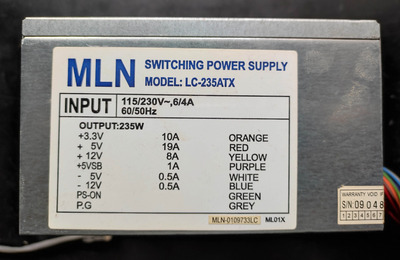
Curious what PSU you are using .... if it is too new the board may not like it. Have a few older slot 1 etc that anything newer than ATX 12v 2.03 won't work, fans spins and plays dead.
Most newer psu are ATX 12v spec 2.3 or higher iirc. Just a thought.

Hate posting a reply and then have to edit it because it made no sense 😁 First computer was an IBM 3270 workstation with CGA monitor. Stuff: https://archive.org/details/@horun

Reply 33 of 36, by butjer1010

User metadata
Rank Member
Rank
Member
Horun wrote on 2024-04-23, 03:21:

Curious what PSU you are using .... if it is too new the board may not like it. Have a few older slot 1 etc that anything newer than ATX 12v 2.03 won't work, fans spins and plays dead.
Most newer psu are ATX 12v spec 2.3 or higher iirc. Just a thought.

I didn't think about that, yes, it is a new psu 🙁
Will try with older one and let You know, Thanks

Edit:
Nope, i tried with one made in 2001. - same!

Attachments

  • IMG_20240423_091252.jpg
    Filename
    IMG_20240423_091252.jpg
    File size
    659.47 KiB
    Views
    88 views
    File license
    Fair use/fair dealing exception

Reply 34 of 36, by butjer1010

User metadata
Rank Member
Rank
Member
rasz_pl wrote on 2024-04-22, 22:14:
TLDR version is: "-INx -Analog Input pins (pages 4-7)." […]
Show full quote

TLDR version is:
"-INx
-Analog Input
pins (pages 4-7)."

I'm not an electrician, there is so much things i don't understand there. Should i measure resistance from this "table", or only voltages? For example, on pin 2 it says : OD 10K-3V-up - Open-drain with 10Kohm 3V pull-up, 8mA sink current. What to measure here? 10K or 3V, what can cause the problem?
Thanks

Reply 35 of 36, by rasz_pl

User metadata
Rank l33t
Rank
l33t

"measure (DC voltage mode, 5V range)"

make a list with pin number and measurement. Start with pins 67-70 and 79-94, 38 and 47 are also interesting.
It does look like both -5V and -12V are used for reference voltage for thermistors? Weird.

Open Source AT&T Globalyst/NCR/FIC 486-GAC-2 proprietary Cache Module reproduction

Reply 36 of 36, by butjer1010

User metadata
Rank Member
Rank
Member
rasz_pl wrote on 2024-04-23, 13:14:

"measure (DC voltage mode, 5V range)"

make a list with pin number and measurement. Start with pins 67-70 and 79-94, 38 and 47 are also interesting.
It does look like both -5V and -12V are used for reference voltage for thermistors? Weird.

Ok, thanks a lot!!!