Here are my findings after a couple of days of tinkering.
1) The main things I'd like to change are clock and multiplier, since I'll be using different 486 cpus with this board.
2) I tried both DX, DX2 and DX4 cpus.
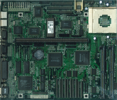
For 1), I believe that the clock generator is an MX8315 in SOP 14 surface mounted package configuration, since it is near the crystal oscillator working at 14.318. Here are its specifications:
http://bitsavers.trailing-edge.com/components … ator_199309.pdf
Specifically, I believe clock is determined by whether pins S0-S2 are set to high or low. Normally I would guess these are set through jumpers, but in this board they are connected to 472 resistors and then ground. Would those resistors be used to filter interference coming from ground? As per the previous specifications, S0-S2 set to zero mean 33.3 Mhz clock, which corresponds to what I see on the board. Do you think that there is any way to operate on those pins, or is it common to have them factory-set to a specific hardware configuration in OEM boards?
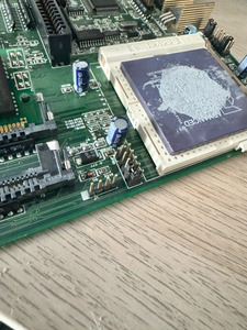
Regarding 2), I believe the star of the show is the factory-unpopulated JP20 on the side of the board. I found that one of the pins is connected to R17 in the cpu socket. By putting a jumper on the pins shown in picture, I was able to set the 100mhz AMD DX4 to DX2 operation (strangely, 33.5*2=67.1Mhz). Moreover, Intel 486DX works out of the box with no modifications to voltage pins. I have also tested that the VOLDET pin works correctly and outputs 3.3 or 5V depending on the CPU installed. Weirdly, AMD 486 DX2-66V15BGC does not respond to the jumper modification outlined above and always runs at 3X multiplier.
Based on the above, any ideas or observations would be greatly appreciated.