VOGONS


First post, by popcalent

User metadata
Rank Newbie
Rank
Newbie

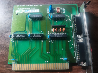
I'm trying to make a PC104 Game Card and I'm using a regular 8-bit ISA Game Card schematic for reference and an actual 8-bit ISA Game Card with a voltmeter for reference.

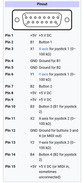
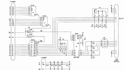
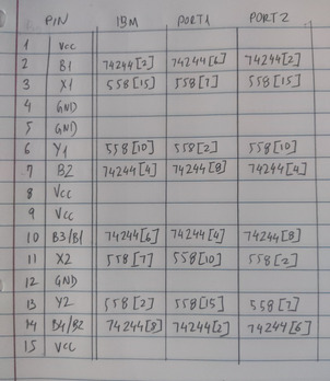
The schematics of the IBM manual, and what I found out with the voltmeter don't match. The last picture shows a table where the first column is the game port pinout, the second column is the connections shown in the IBM manual, the third column is the connections of port 1 of my card, and the fourth column is the connections of port 2 of my card.

For instance, pin 2 of the IBM port is connected to pin 2 of the 74244 and it's represented as 74244[2].

None of the two ports on my board matches the IBM port... Port 2 is almost the same as the IBM port, but has two buttons reversed, and X2 and Y2 coordinates reversed. So what is it? What's the correct thing?

IMG_20240507_044928.jpg
Filename
IMG_20240507_044928.jpg
File size
1.55 MiB
Views
152 views
File license
Fair use/fair dealing exception
Screenshot_2024-05-08-02-25-26-521_com.android.chrome-edit.jpg
Filename
Screenshot_2024-05-08-02-25-26-521_com.android.chrome-edit.jpg
File size
55.51 KiB
Views
152 views
File comment
Wikipedia
File license
Fair use/fair dealing exception
Screenshot_2024-05-08-02-44-31-568_com.google.android.apps.docs-edit.jpg
Filename
Screenshot_2024-05-08-02-44-31-568_com.google.android.apps.docs-edit.jpg
File size
118.52 KiB
Views
152 views
File comment
IBM Game Control Adapter Manual
File license
Fair use/fair dealing exception
IMG_20240508_060827.jpg
Filename
IMG_20240508_060827.jpg
File size
1.07 MiB
Views
98 views
File license
Fair use/fair dealing exception
Last edited by popcalent on 2024-05-08, 11:15. Edited 1 time in total.

Reply 1 of 3, by Rwolf

User metadata
Rank Member
Rank
Member

I think the two-port cards like that were intended for either two joysticks with 2-axis and 2 buttons each, the sticks attached to one connector each,
or a single joystick with 4 axis and 4 buttons, attached to either one *or* the other connector.

Reply 2 of 3, by popcalent

User metadata
Rank Newbie
Rank
Newbie
Rwolf wrote on 2024-05-08, 08:36:

I think the two-port cards like that were intended for either two joysticks with 2-axis and 2 buttons each, the sticks attached to one connector each,
or a single joystick with 4 axis and 4 buttons, attached to either one *or* the other connector.

That would make sense if coord X1 of one port was connected to coord X2 of the other. Instead, coord X1 of one port is connected to coord Y2 of the other port and so on, it doesn't make any sense...

Reply 3 of 3, by Rwolf

User metadata
Rank Member
Rank
Member

Perhaps then some legacy non-std pinout on a stick they wanted to support?
There were some non-pc 'joypads' (I never had one) that might apply.

Some pinout variants: https://allpinouts.org/pinouts/connectors/inp … ck-pc-gameport/