VOGONS


Reply 500 of 543, by mockingbird

User metadata
Rank Oldbie
Rank
Oldbie
Paar wrote on 2024-03-06, 17:43:

I have some news about my project. With a help of member of retro web Discord channel, I've been able to disable internal keyboard controller and enable external one. So the keyboard works great with external KBC, unfortunately once I connect PS2 mouse, the keyboard stops responding right after POST screen (it works OK before that). As Octek Hippo 10 has solder footprints for PS2 connectors for keyboard and mouse, and keyboard works great when mouse is not connected, I assume I have something wired wrong. More research is to be done.

I think it's the same issue on the UM4980... It works with the external KBC (once you set the jumper), but then stops working with the interposer connected. I'm looking forward to your fix.

mslrlv.png
(Decommissioned:)
7ivtic.png

Reply 501 of 543, by Paar

User metadata
Rank Member
Rank
Member

Hmm, something weird is going on. After some more testing, the system hanged after POST even without PS2 mouse connected (but worked in BIOS every time). And after I was able to boot to DOS with both KB and PS2 mouse connected, unfortunately I couldn't detect the mouse with CuteMouse app.
I have a bunch of Amikey 2 KBCs from ebay which use for testing and I'm not 100% sure they're OK. I need to test them in another system to be sure.

Reply 502 of 543, by mockingbird

User metadata
Rank Oldbie
Rank
Oldbie
Paar wrote on 2024-03-06, 18:38:

Hmm, something weird is going on. After some more testing, the system hanged after POST even without PS2 mouse connected (but worked in BIOS every time). And after I was able to boot to DOS with both KB and PS2 mouse connected, unfortunately I couldn't detect the mouse with CuteMouse app.
I have a bunch of Amikey 2 KBCs from ebay which use for testing and I'm not 100% sure they're OK. I need to test them in another system to be sure.

Do you have the regular interposer from MaxTheRabbit? I can send you one if it helps you in your endeavour.

mslrlv.png
(Decommissioned:)
7ivtic.png

Reply 503 of 543, by Paar

User metadata
Rank Member
Rank
Member

With Octek Hippo 10 I don't need one as all is there for PS2 mouse support. I think I'm close to figuring it out but have to make more experiments and measurements.
I have those interposers, planning to use them for different boards. The main goal of this project is to get an understanding how disabling of internal KBC works. With that and a proper poinout, this interposer should be usable on all UM8498F boards with external KBC option.

Reply 504 of 543, by Paar

User metadata
Rank Member
Rank
Member

More progress. As I have discovered, boards with this UMC chipset don't have 7406 inverters present because there is a built in inverter inside UM8496F chip. And what do you know, I didn't have KBCI a MSCI hooked properly, needed to bridge some resistor points on the board.
The good news is the system is now stable and boots up every time, be it with PS2 mouse connected or not.
The bad news is the CuteMouse is still not able to detect the mouse. I have to double check that everything is connected as it should.

Reply 505 of 543, by feipoa

User metadata
Rank l33t++
Rank
l33t++

I finally got around to assembling a KBC-PS2 unit based on maxtherabbit's PCB v3. A drafting of this is shown below:

00-PS2_maxtherabbits_PCB_for_native_PS2-KBC.png
Filename
00-PS2_maxtherabbits_PCB_for_native_PS2-KBC.png
File size
74.37 KiB
Views
640 views
File license
Fair use/fair dealing exception

At first I was confused because the rendering shows the headers placed on the same surface as the components, but it looks like the rendering was intending to show both surfaces on the same view. Thus, headers and components are on opposing sides of the PCB.

I laid out the parts needed and soldered on a wire to the ISA slot corresponding to IRQ 12:

01-PS2_materials.JPG
Filename
01-PS2_materials.JPG
File size
409.58 KiB
Views
640 views
File license
CC-BY-4.0

One of my grievances with most modern home-brew projects, is people using oversized pins going into DIP sockets. As a recap from my comments earlier in the thread, the:

width of a keyboard controller's pins, that is, the width in the direction of spring deflection, is: 0.26 - 0.30 mm
1) standard 2.54 mm spaced square headers: 0.64 mm
2) round machine pins: 0.61 mm
3) medium (standard?) round machine pins: 0.54 mm
4) smaller round machine pins: 0.45 mm
5) tapered thin Arduino pin headers: 0.35 mm

I went with the last option above because the pin width is the closest to what a DIP socket expects. The parts were cheap, readily available, and did not substantially increase assembly time. Below is an image of the jig I used for assembly:

02-PS2_thin_pin_assembly.JPG
Filename
02-PS2_thin_pin_assembly.JPG
File size
238.23 KiB
Views
640 views
File license
CC-BY-4.0

The DIP-40 socket on the bottom is just to set the pin alignment and pin depth while soldering. Same with the top most header, which is connecting two 1x10 Arduino headers. Some light sanding was required on the black ABS so that the pins aligned without being forced. If you can find a 1x20 Arduino header, then this step isn't required.

Solder the Arduino headers, then cut the leads and remove the temporary DIP-40:

03-PS2_thin_pin_soldered_1.JPG
Filename
03-PS2_thin_pin_soldered_1.JPG
File size
379.37 KiB
Views
640 views
File license
CC-BY-4.0

Turning the PCB over, this is what the pins look like:

04-PS2_thin_pin_soldered_2.JPG
Filename
04-PS2_thin_pin_soldered_2.JPG
File size
361.62 KiB
Views
640 views
File license
CC-BY-4.0
Last edited by feipoa on 2024-03-12, 05:35. Edited 1 time in total.

Plan your life wisely, you'll be dead before you know it.

Reply 506 of 543, by feipoa

User metadata
Rank l33t++
Rank
l33t++

Next, if you want your KBC socket or KBC (without socket) to sit level and as low as possible, you can sand down the section of the pins which would otherwise touch the bottom of the KBC or KBC socket. You only need to sand down the 1x20 row which sits under the KBC:

05-PS2_thin_pin_sanded_.JPG
Filename
05-PS2_thin_pin_sanded_.JPG
File size
315.57 KiB
Views
640 views
File license
CC-BY-4.0

Next, solder on the DIP-40 socket, if you want your adaptor socketed, or solder on the KBC directly if you don't want it socketed:

06-PS2_assembled_top.JPG
Filename
06-PS2_assembled_top.JPG
File size
1.48 MiB
Views
640 views
File license
CC-BY-4.0

Connect your PS/2 bracket and the keyboard controller chip:

08-PS2_final_top.JPG
Filename
08-PS2_final_top.JPG
File size
300.75 KiB
Views
640 views
File license
CC-BY-4.0
09-PS2_final_bottom_1.JPG
Filename
09-PS2_final_bottom_1.JPG
File size
386.15 KiB
Views
640 views
File license
CC-BY-4.0

Attachments

Plan your life wisely, you'll be dead before you know it.

Reply 507 of 543, by feipoa

User metadata
Rank l33t++
Rank
l33t++

Another view of the unit:

10-PS2_final_bottom_2.JPG
Filename
10-PS2_final_bottom_2.JPG
File size
326.11 KiB
Views
632 views
File license
CC-BY-4.0

This is what I measured for the header pinouts:

11-PS2_header_pinout.JPG
Filename
11-PS2_header_pinout.JPG
File size
37.64 KiB
Views
632 views
File license
CC-BY-4.0

I've circled the 7406 inverter pins which have traces going to them. If I recall correctly, I used only 3 inverters on my prototype, but it looks like maxtherabit is using 4 inverters. I haven't bothered to check what the extra inverter is wired to.

Here comes the disappointing part of my journey with the adaptor. While the max's variant of this adaption is functional, the particular motherboard I wanted to put it in had obstructions - not in one, but in two directions. First, the pin header overhang was too far as it hits the ISA slot:

12-PS2_fitment_struggles_1.JPG
Filename
12-PS2_fitment_struggles_1.JPG
File size
421.95 KiB
Views
632 views
File license
CC-BY-4.0

Next, the offset overhang was too far - hits the BIOS. I could probably fudge this if I had to, but it wouldn't matter because the ISA slot is still in the way.

13-PS2_fitment_struggles_2.JPG
Filename
13-PS2_fitment_struggles_2.JPG
File size
358.7 KiB
Views
632 views
File license
CC-BY-4.0

If there are plans for another PCB design, having the PS/2 pin header as a single row would help for the situation with my motherboard (possibly others too?). IRQ12 could also be in the same row, but with a space between the PS/2 block and the IRQ12 block.

Plan your life wisely, you'll be dead before you know it.

Reply 508 of 543, by feipoa

User metadata
Rank l33t++
Rank
l33t++

How do I know my assembly was functional - I stacked two DIP-40 sockets to just clear the ISA slot.

14-PS2_fitment_stacked_solution.JPG
Filename
14-PS2_fitment_stacked_solution.JPG
File size
296.69 KiB
Views
632 views
File license
CC-BY-4.0

Due to the lack of elegance in the stocked sockets, I elected to put one of my own KBC-PS2 units onto this particular motherboard. The spacing was such that my PS/2 header cleared the ISA slot.:

15-PS2_replacement.JPG
Filename
15-PS2_replacement.JPG
File size
557.94 KiB
Views
632 views
File license
CC-BY-4.0

I had to pull my KBC-PS2 unit out of Baby Screamer board, so I put the maxtherabbit design into the Baby Screamer:

16-PS2_moving_adaptor_VIA.JPG
Filename
16-PS2_moving_adaptor_VIA.JPG
File size
552.29 KiB
Views
632 views
File license
CC-BY-4.0

Unfortunately, when I powered up the Baby Screamer, I heard only beeping. Replacing the KBC with a Holtek resolved that:

17-PS2_moving_adaptor_HOLTEK.JPG
Filename
17-PS2_moving_adaptor_HOLTEK.JPG
File size
628.16 KiB
Views
632 views
File license
CC-BY-4.0

Side-by-side of max's adaptor next to my original prototype. EDIT: pin offset messed up. Anyone replicating this setup should not follow this photo's lead placement.

20-PS2_sidebyside.JPG
Filename
20-PS2_sidebyside.JPG
File size
325.31 KiB
Views
459 views
File license
CC-BY-4.0

One other change I'd consider would be to use 0805 inductors rather than 1210's. Based on max's selection of a 470 uH inductor, I can see why he went with 1210, that is, because 470 uH doesn't come in 0805. We discussed earlier that the exact value of 470 uH isn't a requirement. I've been using 2.2 uH and 10 uH inductors without issue. The reason why smaller inductors might be of benefit is that I can see situations in which the DIP keyboard socket on a motherboard has tall DIP style IC's inside the socket. The height of the 1210 470 uH are usually about 2.4 mm, and if there's a DIP inside an existing KBC socket, the inductor may hit the TTL, preventing full insertion. An 0805 like LQM21PN2R2MC0D (this is 2.2 uH) is 0.55 mm tall, or CBL2012T100M (this is 10 uH) at 1.0 mm tall. The seated height of the 7406 is about 1.65 mm, so going any shorter than that might not yield any further optimisation. If bypassing the motherboards KBC DIP socket entirely, then going shorter on the component heights would bring the adaptor closer to the motherboard. This may be beneficial for keyboard controllers located in a blocking view of ISA slots. Nonetheless, I think certain 0805 inverters should be solderable to the existing PCB; I just don't have any.

Last edited by feipoa on 2024-03-12, 08:59. Edited 2 times in total.

Plan your life wisely, you'll be dead before you know it.

Reply 509 of 543, by feipoa

User metadata
Rank l33t++
Rank
l33t++

Below is a 386 motherboard with some TTL's under the keyboard controller socket: EDIT: pin offset messed up. Anyone replicating this setup should not follow this photo's lead placement.

18-PS2_TTL_under_DIP.JPG
Filename
18-PS2_TTL_under_DIP.JPG
File size
370.57 KiB
Views
459 views
File license
CC-BY-4.0

With my current pin lengths, the height of the inductors prevents full insertion by 0.7 mm. Swapping the 1210 inductors with shorter height 0805's (2.2 - 10 uH) will allow for full insertion. Unfortunately, I don't have anything else I need to order from digikey at the moment, so this will have to wait.

As a quick fix, I have made a third adaptor with the leads longer by about 1 mm: EDIT: pin offset messed up. Anyone replicating this setup should not follow this photo's lead placement.

19-PS2_right_side_longer_pins.JPG
Filename
19-PS2_right_side_longer_pins.JPG
File size
194.66 KiB
Views
459 views
File license
CC-BY-4.0

I suspect the original idea behind placing the IC's on the bottom of the PCB was due to there being a pin header block (4.3 mm tall) below the PCB, which would negate any component heights. At any rate, the issue is nil if both the adaptor and the KBC are directly soldered, that is, the MB has no socket and the adaptor has no socket. If the adaptor is placed behind an ISA slot, is there enough clearance for one DIP-40 socket somewhere - either a socket on the MB, or a socket on the adaptor?

Overall, I'm pretty pleased with the outcome. The assembly time of maxtherabit's adaptor is substantially less than the time it takes to assemble my units. I've made 3 of my adaptor prototypes and 3 of maxtherabits. Nit picking heights aside, the main issue I ran into was the pin header cantilever on max's unit.

Last edited by feipoa on 2024-03-12, 09:01. Edited 2 times in total.

Plan your life wisely, you'll be dead before you know it.

Reply 510 of 543, by maxtherabbit

User metadata
Rank l33t
Rank
l33t

I made it as small as I could, but no matter how I orient the protrusions someone will complain simply because there are so many different boards out there - no matter what you do it will interfere with something on one of them.

As for changing the pin header to single row, that's one thing I will not entertain. The 2x4 layout is the only thing resembling a standard for ps/2 pinout (it is the same footprint as the pins of a mini-DIN socket would be)

You're right about the insulation height on the bottom being expected to negate the SMD component height. My build target was the "smaller round machine pins: 0.45 mm". Yes technically these are marginally wider than a DIP leg would be, but I can confidently say from experience they do not permanently deform the socket wipes.

Reply 511 of 543, by Paar

User metadata
Rank Member
Rank
Member

When modifying a board which has KC soldered in, it's probably the best to use machined pins and socket. Classic pin headers are not ideal for use in socket - they either won't fit the machined ones or will deform the classic ones.
I'm more interested in making this adapter work with KBCs beside ISA slots and I think the current interposer solution - while it works somehow - is not ideal. I plan creating something different and will share my schematics and PCB design on Github when it's ready.

EDIT: I find the idea of using Arduino style connectors for adapter pins genius and will try to use it myself. I am able to buy 40pin ones so the assembly should be a breeze.

Last edited by Paar on 2024-03-11, 20:41. Edited 1 time in total.

Reply 513 of 543, by feipoa

User metadata
Rank l33t++
Rank
l33t++
maxtherabbit wrote on 2024-03-11, 16:25:

The 2x4 layout is the only thing resembling a standard for ps/2 pinout (it is the same footprint as the pins of a mini-DIN socket would be

There was no standard PS/2 header format amongst motherboard manufacturers. I've come across 1x6, 1x5, 2x4, and 2x5, all with different pinouts within those same footprints. Even miniDIN-6 cable's I've ordered from the same batch did not arrive with consistent header sizes, pin placements, or wire colour consistency. Someone will still have to shuffle the pins around, and if they are already soldering components onto a PCB, moving pins around is but a trivial final step.

maxtherabbit wrote on 2024-03-11, 16:25:

As for changing the pin header to single row, that's one thing I will not entertain.

haha, it's OK. I will modify the gerbers if I keep running into this issue; it is but a very minor alteration. The optimal configuration is as small a protrusion as possible to fit as many scenarios as practical.

It would be greatly appreciated if you could edit out some of the emotion from your responses before submitting. I continue to see snappy, somewhat agitated replies from you; it is not just me, but other members have also PM'ed me about some of your abrasive replies as well. There are more neutral ways of wording sentences which portray the same underlying message.

Paar wrote on 2024-03-11, 18:46:

I find the idea of using Arduino style connectors for adapter pins genius and will try to use it myself. I am able to buy 40pin ones so the assembly should be a breeze.

Glad you liked it. It is closest option to match a standard KBC lead thickness. Keep in mind, though, that not all Arduino pin headers are of the skinny type. Check the photos carefully before you buy. I think some are the standard fat squares. I've only found the skinny style which have those black female connectors on the other end.

Plan your life wisely, you'll be dead before you know it.

Reply 514 of 543, by feipoa

User metadata
Rank l33t++
Rank
l33t++

I messed up the lead placement on my second two max-adaptors and have made EDIT notes on these photos. Anyone replicating the max-adaptor using my photos should not follow lead placements on the last 3 photos shown above. I'll try to get these fixed.

The strange thing was that I was using my correct photo as a guide for my next two assemblies, and I still goofed it up. Powered up the desolder station and began corrective measures:

21-PS2_replacing_leads.JPG
Filename
21-PS2_replacing_leads.JPG
File size
522.26 KiB
Views
458 views
File license
CC-BY-4.0

I thought it would make for an interesting challenge to reuse some of the thin Arduino pins:

22-PS2_replacing_leads.JPG
Filename
22-PS2_replacing_leads.JPG
File size
547.04 KiB
Views
458 views
File license
CC-BY-4.0
23-replacing_leads.JPG
Filename
23-replacing_leads.JPG
File size
400.57 KiB
Views
458 views
File license
CC-BY-4.0

It came out acceptable, but I could not manage to get the leads all the same length. The photo on the right is the pins I reused, while the photo on the left, I just pulled some fresh Arduino pin headers. The unit on the left is intentionally with shorter leads, while the right intentionally with longer leads:

19b-PS2_right_side_longer_pins.JPG
Filename
19b-PS2_right_side_longer_pins.JPG
File size
316.04 KiB
Views
458 views
File license
CC-BY-4.0

And the corrected side-by-side comparison if my prototype next to max's PCB.

Attachments

Plan your life wisely, you'll be dead before you know it.

Reply 515 of 543, by feipoa

User metadata
Rank l33t++
Rank
l33t++

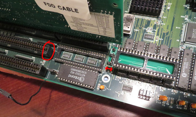
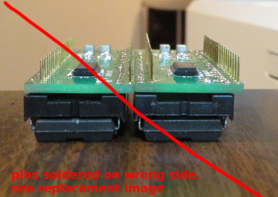
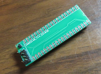
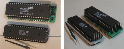
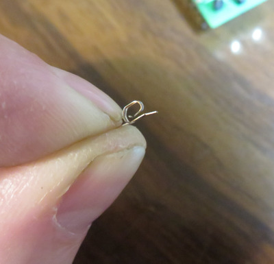
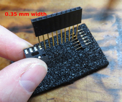
An interesting consequence of trying to reuse the thin Arduino pins was that I accidentally inserted one of the leads rotated 90 degrees. Oops! I pulled the lead out, but the spring in the DIP socket did not restore to its home position:

A-Spring_deflection_0.54mm.JPG
Filename
A-Spring_deflection_0.54mm.JPG
File size
227.19 KiB
Views
457 views
File license
CC-BY-4.0

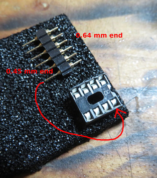
The flat thickness of the Arduino lead is 0.35 mm, while the wide side is 0.54 mm. It was the 0.54 mm that stretched out the spring. Thus, I would gather that machine pins of width 0.54 mm & 0.64 mm, and square pins of width 0.64 mm are not suited for DIP sockets, that is at least, if you ever intend to insert something with smaller pins into the socket at a later time:

B-Spring_deflection_0.54mm.JPG
Filename
B-Spring_deflection_0.54mm.JPG
File size
379.47 KiB
Views
457 views
File license
CC-BY-4.0

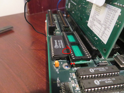
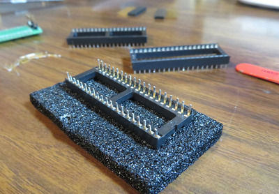
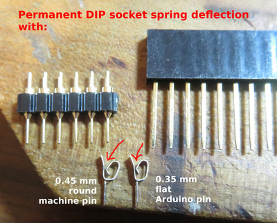
Next, using a new DIP socket, I inserted the smaller round machine pin of diameter 0.45 mm, but it too showed permanent deflection:

C-Spring_deflection_0.45mm.JPG
Filename
C-Spring_deflection_0.45mm.JPG
File size
496.69 KiB
Views
457 views
File license
CC-BY-4.0

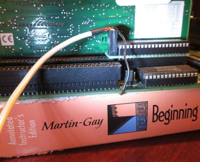
I went on to see how much deflection the 0.35 mm flat Arduino pin caused:

D-Spring_deflection_0.35mm.JPG
Filename
D-Spring_deflection_0.35mm.JPG
File size
330.98 KiB
Views
457 views
File license
CC-BY-4.0

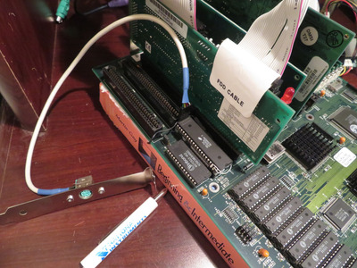
Then compared it with the smallest machine pin here:

E-Spring_deflection_0.45mm_and_0.35mm.JPG
Filename
E-Spring_deflection_0.45mm_and_0.35mm.JPG
File size
1.04 MiB
Views
457 views
File license
CC-BY-4.0

While the 0.35 mm Arduino pin showed the least permanent deflection, the spring did not entirely restore either.

My conclusion would be to use leads with the smallest thickness, down to perhaps 0.25 mm, especially if you ever intend to later install another device with thinner leads, or to put the original keyboard controller chip back. The range of thicknesses for DIP leads on keyboard controllers that I measured were from 0.26 - 0.30 mm. After inserting and removing a 0.26 mm thick chip into a DIP-40 socket, one which had previously been stretched out by 0.45 mm machine pins, it felt noticeably less tight.

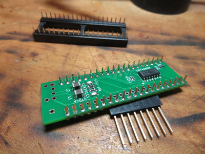
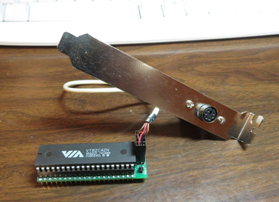
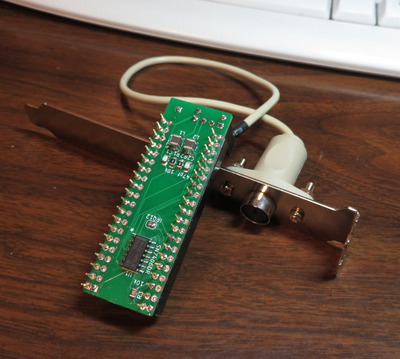
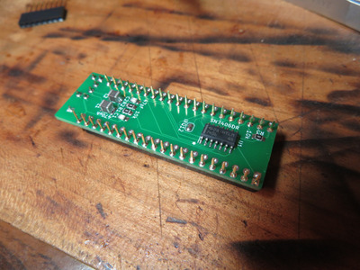
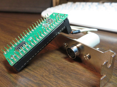
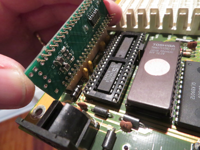
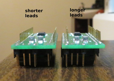
As the lead thicknesses of my prototype PS2-KBC adaptors are only 0.16 mm, I am going to be especially mindful of what I stick into keyboard controller sockets on my various motherboards. Luckily, my proto-PS2-KBC units still worked after having used 0.35 mm pins in the DIP socket, however the fitment is vastly looser :(

Ideally, we'd be using leads of about 0.25 mm thick on these adaptors to preserve our socket's spring force. The flat plate 0.35 mm Arduino pins were the best I could find that would be easy to install. But even if 0.25-0.30 mm thick machine pins are available, you'd still be mating a flat plate socket to a round rod, thus the mating surface area is reduced compared to a thin rectangular lead.

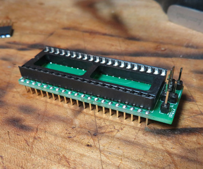
EDIT: If you are like me, you probably have some rare motherboards you don't want to ruin by stretching out their keyboard sockets. I was considering abandoning the max adaptor because even the thin Arduino headers can cause some permanent socket deflection. However, it occurred to me that if you have not yet stretched out your motherboard's KBC socket, you can use a spare DIP-40 socket as a sacrificial mating layer in the middle. It really just depends on everyone's personal threshold for hardware preservation and reversibility.

Plan your life wisely, you'll be dead before you know it.

Reply 516 of 543, by feipoa

User metadata
Rank l33t++
Rank
l33t++

I ran a quick MS-DOS test to see which keyboard controllers work and don't work with PS/2 mice.

On the working list, there was:
Intel/Megatrends KB-BIOS-VER-F
Intel/Megatrends MEGA-KB-F-WP
Holtek HT6542B
VT82C42N
Intel/Megatrends Megakey

Not working, there was:
Lance Corp LT38C41
Winbond W83C42
Acer 90M002A
AMIKEY-2

There may be something wrong with my AMIKEY-2 because these normally work with PS/2 mice.

Attachments

Last edited by feipoa on 2024-04-12, 09:15. Edited 1 time in total.

Plan your life wisely, you'll be dead before you know it.

Reply 517 of 543, by Paar

User metadata
Rank Member
Rank
Member
feipoa wrote on 2024-03-12, 11:38:

There may be something wrong with my AMIKEY-2 because these normally work with PS/2 mice.

Amikey 2 I bought from eBay had working keyboard in PS2 mode, but non-functional mouse. Tried two of them, both were faulty.

Tried Amikey 2 from dead motherboard and that worked like charm.

Reply 518 of 543, by froller

User metadata
Rank Member
Rank
Member
feipoa wrote on 2024-03-12, 11:38:

There may be something wrong with my AMIKEY-2 because these normally work with PS/2 mice.

It certainly is.
AMIKEY-2 is proven to work with PS/2 mice.
And it doesn't require tying Pin26 to +5V as HT6542B does for proper start.

▓▓▓▓▓▓▓▓▓▓▓▓▓▓▓▓▓▓▓▓▓▓▓▓▓▓▓▓▓▓▓▓▓▓▓▓▓▓▓▓▓▓▓▓▓▓▓▓▓▓▓▓ 100%
Virus check complete. All viruses are working properly.

Reply 519 of 543, by maxtherabbit

User metadata
Rank l33t
Rank
l33t
feipoa wrote on 2024-03-12, 02:53:

It would be greatly appreciated if you could edit out some of the emotion from your responses before submitting. I continue to see snappy, somewhat agitated replies from you; it is not just me, but other members have also PM'ed me about some of your abrasive replies as well. There are more neutral ways of wording sentences which portray the same underlying message.

Bro you're seeing something that isn't there, there was no emotion in that post