Reply 24480 of 27502, by BitWrangler

- Rank
- l33t++
Cool, which LCD panels have you ended up with? I've got a Toshiba LTM10C209 and that's an industrial panel that's very tolerant […]
BitWrangler wrote on 2023-06-09, 02:50:Thermalwrong wrote on 2023-06-09, 01:21:Some years ago, my boss at work threw away a little 8" LCD tv from Maplins, which I kept. It could take VGA but looked terrible […]
Some years ago, my boss at work threw away a little 8" LCD tv from Maplins, which I kept. It could take VGA but looked terrible doing it with awkward scaling, but it had a 640 x 480 LCD in it, so I threw away the TV and kept the LCD.
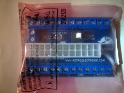
Some months ago I made this PCB for the 44-pin LCD connector that you can find on many industrial PCs and single board computers. Initially I thought it was advantech specific but it seems to be standard across many of the Taiwanese integrators that were making x86 SBCs.
advantech-pca-6145-lcd.jpg
The LCD that I took out of that 8" LCD TV uses a 32-pin flat flex cable with I think 0.5mm pitch pin spacing that's way too small for me to solder, thus this PCB was necessary and it's worked for several other LCD panels but not this little Sharp 8" LCD and I had no idea why. It's been on my 'please fix this at some point' pile for a long time.
It would work with this board but it would show noise on any details on the screen like in the BIOS screen the red & white text would have some break-up here and there. In Windows any details like the start menu were illegible and when doing the Shut down Windows screen which does the cross-hatch thing, the display would just break entirely on displaying that.
Initially I thought it was down to the BIOS on this Advantech PCA6145 and other SBCs that had wrong details to drive this LCD panel since the LCD worked with its original board and the digital picture frame driver boards, where I'd sourced other 640x480 TFT LCDs from digital picture frames. I'm upcycling them 😀Going through it all on the oscilloscope looking at signals I noticed that the picture frame boards did drive the screen at a higher frequency and was trying to figure out if there's a way to make the SBC's BIOS match this, but I couldn't see a way to do that. Then I had a read of yyzkevin's experiences with getting a VGA LCD working with custom wiring: https://www.yyzkevin.com/clock-signal/
I am so glad this information is shared, the frequences matched up to what my SBC was putting out at ~25mhz so maybe there's no way to change the frequency. Also the amplitude of my clock signal was all wrong, 8 volts peak to peak?filtering-for-clock.png
I found that my SBC doesn't implement any filtering on the motherboard for the LCD signals so my PCB should have been doing that. To fix that I cut the trace for the clock signal and started bodging on new parts, to match up what the Chips & Tech CT65550 datasheet specifies for filtering. 220pf capacitor and initially I tried resistors in line, that was bad.
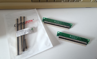
44-pin-lcd-connector.jpg
But then I stole this blue filter thing from a scrap PCB's USB data lines and tested again, now the display is 100% working! I need to figure out what this part is called so I can get a fixed PCB version eventually 😀
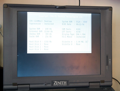
The clock signal looks cleaner on the scope, the display is great now, it even handles the cross-hatch in the Windows shutdown screen, pixel perfect. All it was was just how 'clean' the clock signal is when there are ~20 other signals in total.
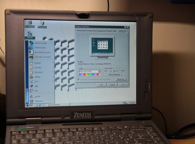
little-sharp-lq080v3dg01-lcd-works.jpg
This means I can start making something to hold this screen and an SBC at last.Thanks Kevin for sharing your experiences with LCD troubleshooting 😀
Nice stuff. I added a couple more photoframes to the pile to play with. Gotta source those ribbon connectors and hookup stuff.
Cool, which LCD panels have you ended up with? I've got a Toshiba LTM10C209 and that's an industrial panel that's very tolerant of the messy signal I was feeding it. But I don't like its colour reproduction.
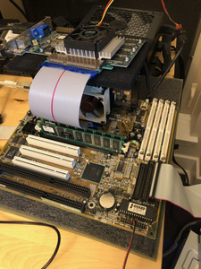
Another interesting one I got that takes a flat-flex cable is the Sharp LQ104DG83 - these Sharp panels look great with nice viewing angles, like this little 8" LCD and like on my Toshiba Satellite 400CS that I upgraded to TFT. This Sharp panel came out of a Texet 10.4" digital picture frame and these are the best made ones I've seen so far. Most of the no-name ones were made as cheap as possible but this one has an ESS ES830FAA chip making the video and a separate TSUM16AK driver board that works like a VGA LCD display with screen controls - hope I can figure out how to get VGA into one of these.Finally got this LQ080V3DG01 behaving with the smaller SBC that I wanted to use it with, this one didn't go so easily. It was still giving noise on complex enough screen:
- In line emi filter on clock line = good improvement, went from unusable to noise on some screens
- Shorter cable = good improvement. This cable is too short but it gives 100% noise-free display
- Bypass capacitor for LCD power = no change
- Changing connector to top opening one = possibly some improvement though that may have been correcting a soldering error for the emi filter.
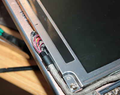
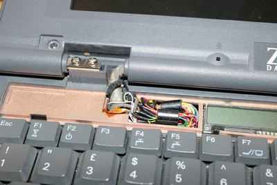
- Adding copper guitar tape to the outside of the 20cm flex cable, with tape around that for insulation = good improvement, clear & stable on windows shutdown screen at last
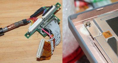
IMG_1440 (Custom).JPG
Very happy with this now, since the LCD is being driven directly by the graphics chip I think there should be less latency than if it was going through a VGA LCD display. A little LCD with a tiny PC104 SBC is my kind of 486.
Once I tidy up the design a bit I can share the PCB design for this adapter board, you'll notice it has a lot of bodges, but since I only had to worry about 5 of them it's easier to re-work what I've got.
Not sure if I mentioned the others when you posted before, only extra one I've got deets for here is Coby DP1052 photoframe that has a LG/Philips LB104 S02 panel in which details seem a little scant for but appears to be RGB 6:6:6 ... another one I picked up was a bust and had LVDS panel... but, just discovered a Johnstown Atom board I have might be able to drive it, so might get bodged to that for an XP system.
I have a few bus buffer chips, I'll have to look up if they are fast enough to clean up signals some. Without getting too analog and into the RF magick, I think it would be desirable to do low pass filters where the entire signal bandwidth is below it, and the glitches above it hopefully get blocked. I dunno if I'm making too much sense at the moment, having a bad brain day.
Unicorn herding operations are proceeding, but all the totes of hens teeth and barrels of rocking horse poop give them plenty of hiding spots.