Voodoo3 repair successful! […]
Show full quote
Voodoo3 repair successful!
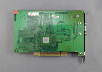
Voodoo3 3000 PCI fixed (no solder mask).jpg
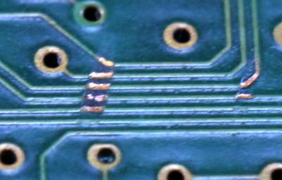
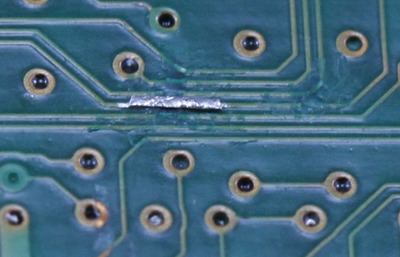
Voodoo3 3000 PCI fixed (no solder mask) closeup.jpg
I started by laying down solder mask to cover the existing exposed traces. Then I scratched out either side of the broken trace, tinned the exposed copper, then soldered a piece of 0.25mm trace overtop.
This was a PITA to try to solder. The tiny piece of copper trace I was using kept floating around in the flux. But eventually got it aligned and tacked down.
Tested with my multimeter and seemed like it had successfully bridged the broken trace.
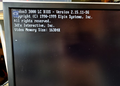
Voodoo3 3000 PCI BIOS startup.jpg
Booting up, it turns out this card is actually a Voodoo3 3000 according to the BIOS startup screen. I had thought it was a 2000 originally, so that was a pleasant surprise. 😁
I haven't put any solder mask on the final repair, as I'm going to test out the card some more first. It might not be completely invisible, but I don't think it looks too bad, even without the solder mask.