Reply 23720 of 27521, by Kahenraz

Rank
l33t
- Rank
- l33t
In case anyone wa wondering, Backpack Bantum drives have DOS drivers, but are not bootable.
In case anyone wa wondering, Backpack Bantum drives have DOS drivers, but are not bootable.
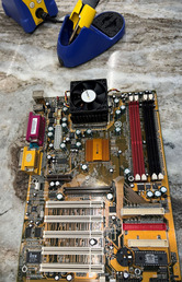
I finally replaced the coin battery holder in this Amptron motherboard. It's been sitting broken for 2+ years. Since I don't have great soldering/desoldering skills, it was just as torturous as I imagined. One leg came right out, and the other took 45 minutes. Of course, the new holder took 30 seconds to put in place.
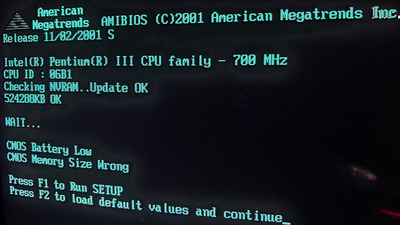
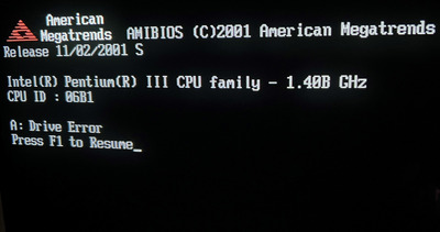
Updated settings are now successfully saved with the new battery securely in place after testing power/no-power.
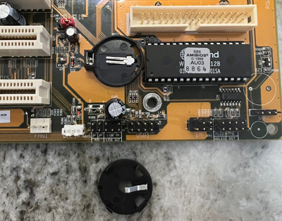
The trouble was probably due to the gigantic ground plane wicking away the heat. Sometimes it can help to warm the surrounding PCB with some hot air first.
Kahenraz wrote on 2023-02-12, 18:24:The trouble was probably due to the gigantic ground plane wicking away the heat. Sometimes it can help to warm the surrounding PCB with some hot air first.
You've probably hit the bullseye; I could feel a large part of the board just to the right of the battery holder getting very warm, which concerned me. And it seemed like the darn iron was never hot enough, but when I changed to the other leg I had immediate success. I finally flipped the board over, cut away the rest of the holder, and then punched the stubborn leg down the other end with the iron.
That is great information. I have a few other boards with bad capacitors, which need replacing, and I'm not dreading replacing them (as much) now. I often run into this problem of a leg taking ages to come off, and at least I have some idea as to why some are such a pain to remove, and others pop right out going forward. I believe the last board work I did took over 8 hours... 8 hours for around 12 capacitors!!!
Thanks!!!!
Meatball wrote on 2023-02-12, 18:32:You've probably hit the bullseye; I could feel a large part of the board just to the right of the battery holder getting very wa […]
Kahenraz wrote on 2023-02-12, 18:24:The trouble was probably due to the gigantic ground plane wicking away the heat. Sometimes it can help to warm the surrounding PCB with some hot air first.
You've probably hit the bullseye; I could feel a large part of the board just to the right of the battery holder getting very warm, which concerned me. And it seemed like the darn iron was never hot enough, but when I changed to the other leg I had immediate success. I finally flipped the board over, cut away the rest of the holder, and then punched the stubborn leg down the other end with the iron.
That is great information. I have a few other boards with bad capacitors, which need replacing, and I'm not dreading replacing them (as much) now. I often run into this problem of a leg taking ages to come off, and at least I have some idea as to why some are such a pain to remove, and others pop right out going forward. I believe the last board work I did took over 8 hours... 8 hours for around 12 capacitors!!!
Thanks!!!!
I have totally been there with the multi-hour cap replacement projects. It is really really helpful to heat up a board first, and of course you should also prevent the board from cooling down too quickly. Sometimes removing large heatsinks can make a huge difference. Whenever I do an extended soldering project I tend to run a medium sized desk fan to keep the smoke out of my face, but I realized at one point that I have to be careful not to direct the fan at the part I'm working on or else it makes it even harder to heat things up.
I haven't tried this yet, but I bet if I heated a board up with a hot air gun (with temperature controls of course) until it was fairly saturated with heat but still able to be touched and then laid it on a folded cotton towel or something else that is insulating it would probably be much easier to work on. I don't know if it'd be worth any additional ESD risk... but it is probably way better than lifting solder pads or damaging traces if a board is being a nightmare to work on.
OH! And there are two weird tools I have found that help me tremendously. I have an old one of these pronged grabber\holder things:
https://www.amazon.com/HTS-191D4-Prong-Jewele … aps%2C96&sr=8-1
I can use that to clip on to the top of an SMD cap, like the little round ones on Voodoo 3 cards, then I can hold on to the tool when soldering or desoldering. Way way easier than trying to use other tools since it can even hold itself upright once you have one leg soldered, but you can still poke the tool a little for fine adjustments.
Also, I found some nice sturdy heat resistant silicone finger tip protectors. I can't remember the brand name of the ones I bought years ago, but these look identical. I see there are lots of different ones on Amazon, but I'm not sure if they are thick enough to be useful. Basically, with those I can pull or push on larger caps\components as I'm heating them up without having to fiddle blindly with a pair of pliers on the opposite side of a board. Without protectors it can be a pretty irritating job depending on the shape of the part and the angle\space you have to work with.
Now for some blitting from the back buffer.
The issue I have with these large ground planes isn't so much removing the leads; those can just be heated up and pulled out. It's the solder that gets stuck in the hole. No amount of heat, suction, or even heated vacuum pumps will work for some holes, and overworking it often ends up damaging or lifting the pad.
The best solution I found that was the easiest on the board is to apply new solder (which also has fresh flux) as a blob, then heat up the blob and let the thermal mass allow the leg to come out gently, without pressing hard into the PCB or the pad. Leave the blob on there and use it as a means to heat up both the pad and the via as you feed in a fresh leg through the hole.
The large thermal mass provides a good thermal connection to the via, and allows the insertion of the new leg. The only caveat is that you will have to rock the component in from one leg to another, if you only have an iron. It might work better with hot tweezers, but a proper set is expensive, and my tweezers are junk. It works fine with an iron though. Just pre-clip the leads to about half their normal height so that it will be easier to get in.
The hardest parts I have to remove are the large through-hole packages. There's no other way to get them off other than levering them, even if you use a pump, hot air, or whatever. I always worry about the pressure I'm putting on the board when I do that, and the fragility of the pads. It's also possible to clip all of the legs off and then they come out easy, but this is not useful when you are debugging the board or adding sockets to known-good chips.
Kahenraz wrote on 2023-02-12, 21:35:The issue I have with these large ground planes isn't so much removing the leads; those can just be heated up and pulled out. It […]
The issue I have with these large ground planes isn't so much removing the leads; those can just be heated up and pulled out. It's the solder that gets stuck in the hole. No amount of heat, suction, or even heated vacuum pumps will work for some holes, and overworking it often ends up damaging or lifting the pad.
The best solution I found that was the easiest on the board is to apply new solder (which also has fresh flux) as a blob, then heat up the blob and let the thermal mass allow the leg to come out gently, without pressing hard into the PCB or the pad. Leave the blob on there and use it as a means to heat up both the pad and the via as you feed in a fresh leg through the hole.
The large thermal mass provides a good thermal connection to the via, and allows the insertion of the new leg. The only caveat is that you will have to rock the component in from one leg to another, if you only have an iron. It might work better with hot tweezers, but a proper set is expensive, and my tweezers are junk. It works fine with an iron though. Just pre-clip the leads to about half their normal height so that it will be easier to get in.
The hardest parts I have to remove are the large through-hole packages. There's no other way to get them off other than levering them, even if you use a pump, hot air, or whatever. I always worry about the pressure I'm putting on the board when I do that, and the fragility of the pads. It's also possible to clip all of the legs off and then they come out easy, but this is not useful when you are debugging the board or adding sockets to known-good chips.
I agree 100% and I have experienced the same things. That last bit of solder that won't come out can be infuriating.
It's one of the reasons I actually enjoy working on really board boards. They seem to not have that problem at all, probably because the holes are often larger and the boards don't hold as much heat.
Now for some blitting from the back buffer.
It's definitely a bigger problem with multi-layer boards. Absolutely forget about cleaning out the vias on a video card, especially late NVIDIA and ATI boards. Just pull them out and pray you can the new legs back in. Those ground planes are dense! A pre-heater is highly recommended!
Kahenraz wrote on 2023-02-12, 21:35:The issue I have with these large ground planes isn't so much removing the leads; those can just be heated up and pulled out. It's the solder that gets stuck in the hole. No amount of heat, suction, or even heated vacuum pumps will work for some holes, and overworking it often ends up damaging or lifting the pad.
I find the easiest way to remove leftover solder in the holes is heating from both sides. Apply a soldering iron on one side to heat up the solder and heated desoldering pump on the other side to remove it.
Adding a little bit extra leaded solder first helps too.
Depending on the amount of copper in the PCB, this does not always work.
Exploring this old Toshiba 1807-S205 I rescued from a thrift store. Not quite "vintage" but old and intriguing.

This one's real interesting, it looks to be one of the last that used Toshiba's in-house bios, and even the old 80's/90's T series laptop diagnostic exes work on it.
Funnily it follows Toshiba's strangeness, and they put a desktop class P3 processor in there. Will upgrade from the celery to a proper Coppermine P3 later.
That's a great keyboard layout for a laptop; it happens to be my favorite 14" layout. How loud is the fan if they are using a desktop Pentium 3?
The fan usually runs at full blast and isn't too loud. It's about average loudness for a laptop.
This was a picture for "proof" of desktop CPU I grabbed when I was trying a Coppermine-T:

What I like is there isn't too much to get at the CPU.
Hmm SL5XU ~40W not even lower voltage. Though I've seen up to 60W P4 desktops in "DRP" laptops. Socket 754 desktop chips were common too.
Unicorn herding operations are proceeding, but all the totes of hens teeth and barrels of rocking horse poop give them plenty of hiding spots.
That's still quite a bit of wattage for a laptop. Is still very impressive. Since it's a Coppermine-T, you will have all of the options to experiment with, as long as the BIOS supports it. Although I suspect thatsl a regular Coppermine might not be compatible with the cooler.
Shponglefan wrote on 2023-02-12, 00:21:Replaced some capacitors on this SOYO SY-5EMA+ V1.0 motherboard. […]
Replaced some capacitors on this SOYO SY-5EMA+ V1.0 motherboard.
In initial testing I couldn't get it to POST. One of the 1000 uF caps was budging so decided to de-solder and replace all the 1000uF caps.
After testing them it turns out only the one cap was bad. Oh well, no harm in replacing all them I suppose. At least they now match the other caps on the board. 😁
Not sure if this fixed the issue, but we'll see once I get around to testing the board again.
edited to add:
Didn't fix the problem. Still won't POST. It's getting power, fans spin and various components (including the CPU) get warm. But no POST, no beeps.
Back to the drawing board.
I'd suggest reflashing the BIOS. Wouldn't be the first board appearing dead but a simple reflash could bring back to life.
I had several socket 7 boards with no signs of damage but not POSTing. A reflash with the correct BIOS brang them back to life.
Another slot A even POSTed with beep codes indicating bad memory or graphics card. None of that was the case, after reflashing the BIOS it worked like a charm.
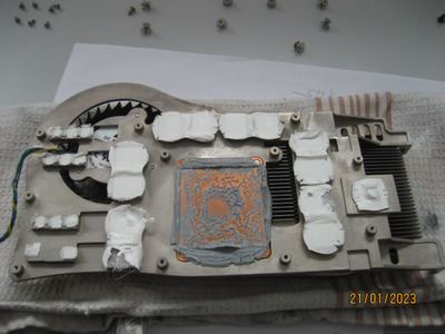
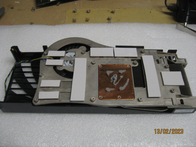
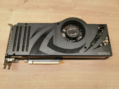
Cleaned the fan, replaced thermal pads and thermal paste on this beast Geforce 8800 Ultra.
Repaired the broken hinge on Compaq Contura Aero 4/33c with the aid of Araldite epoxy resin, and swapped out the broken HDD for CF card.
Turbo -> wrote on 2023-02-13, 21:10:Cleaned the fan, replaced thermal pads and thermal paste on this beast Geforce 8800 Ultra.
Did you use NT-H2 noctua thermal paste not the generic paste? Very important with hot running GPUs.
Thermal Grizzly Hydroanaut is another reasonable price and excellent 11w/mk.
Cheers,
Great Northern aka Canada.
Wdj2005 wrote on 2023-02-13, 22:27:Repaired the broken hinge on Compaq Contura Aero 4/33c with the aid of Araldite epoxy resin, and swapped out the broken HDD for CF card.
I have resorted to that method on some laptops in the past, basically casting the hinge in place with epoxy. Tip, use a precision oiler to get a little inside the hinge's moving parts first, then wipe part that needs to hold glue with alcohol on a cloth. This so that if epoxy goes runny, as it sometimes does while the chemical reaction gets going for the curing process, but before it has progressed enough to make it gel, it does not wick into the hinge, and the alcohol on a wipe to get any oil trace off the parts you need to glue to, and not spraying it or having the wipe sopping wet or it just goes and displaces the oil.
Further tips... if the plastic had turned to cheese/chocolate type consistancy and crumbled away a lot on the corner or edge, you can build a dam around it with modelling clay to contain the epoxy while it sets. If the plastic is ABS, any crumbs saved and any that can be scavenged from flash or structurally insignificant parts inside the shell can be ground up and dissolved in Acetone or Methy Ethyl Ketone (MEK) for pasting over the repairs, either as a putty, or as more or less a matching paint if the epoxy fills to the level of original. If you don't have matching plastic for this, you can attempt to color match by grinding legos or other convenient ABS source.
Unicorn herding operations are proceeding, but all the totes of hens teeth and barrels of rocking horse poop give them plenty of hiding spots.