VOGONS


First post, by carlostex

User metadata
Rank l33t
Rank
l33t

Hi folks,

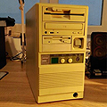
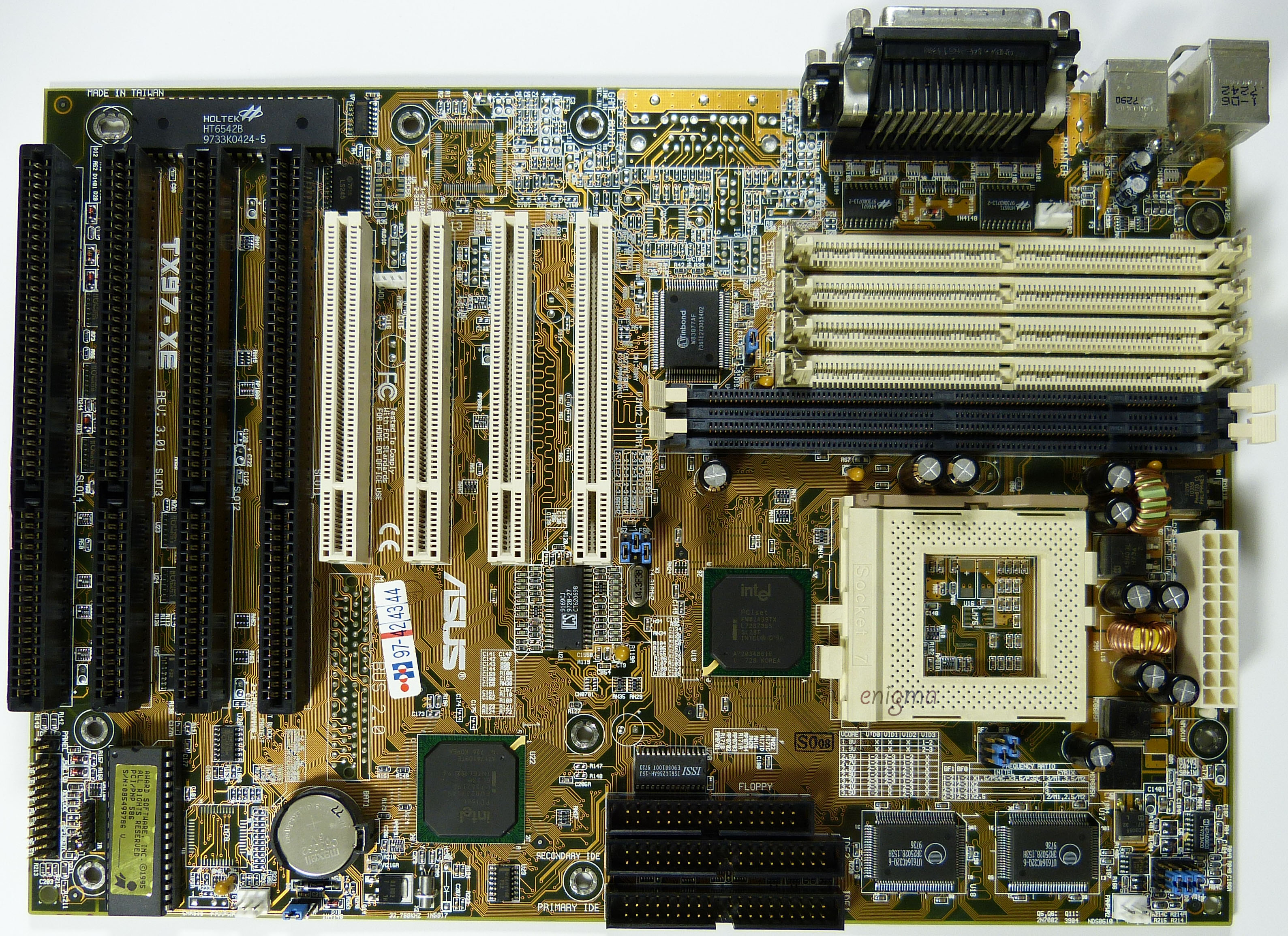
yesterday i set myself to recap my ASUS TX97-XE. It went fine i replaced all VRM caps, some of which were bulged. It was tough to get the old solder to get out but finally i was able to finish the job.

So when i power it on i got repeated beeps in an endless loop. This indicates a RAM issue. Hmmm again? Several weeks ago i had to order DIMM sticks because the exact same had happened. But as soon as i got replacements, i put one in and the system worked normally again.

This time i tried all the sticks i have and still the endless loop kept on going. So i tried clearing the CMOS and the strangest thing happened, the motherboard is now apparently stuck in sleep mode. The power light is blinking constantly, the system does not respond to the power button anymore so i have to reach and turn the machine on the PSU button. I also had the idea of trying the SIMM slots instead of DIMM, but to be honest i don't think it matters anymore.

My guess is that i have now a corrupted BIOS. I even tried a different CPU and nothing. The CPU's don't even get warm. 😵

I must have done something wrong during the recap, i'm thinking of ESD although i'm always careful when messing around with boards.

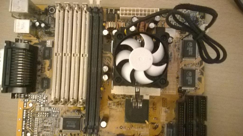
EDIT: Actually i tried touching the CPU removing the fan and it is a little warm, probably around 30ºC but still...

Reply 1 of 17, by kanecvr

User metadata
Rank Oldbie
Rank
Oldbie

Had a simmilar thing happen to me on two occasions. On one board accidentally installed a capacitor backwards... + to - and vice versa. Similar symptoms. I had to take off four caps before I could find the one I installed backwards. On another board I had to replace a couple of damaged tantalum caps (physical damage). One of them had a lead very close to some traces. While replacing cap, I accidentally created a short between it's (-) lead and some of the traces inside the PCB. I managed to fix it by soldering the capacitor superficially after sucking out all the solder in the hole it went in, and soldering it on top a the trace that led to the hole it's (-) lead was supposed to go in to. Real pain in the ass but it worked.

Reply 2 of 17, by carlostex

User metadata
Rank l33t
Rank
l33t
kanecvr wrote:

Had a simmilar thing happen to me on two occasions. On one board accidentally installed a capacitor backwards... + to - and vice versa. Similar symptoms. I had to take off four caps before I could find the one I installed backwards. On another board I had to replace a couple of damaged tantalum caps (physical damage). One of them had a lead very close to some traces. While replacing cap, I accidentally created a short between it's (-) lead and some of the traces inside the PCB. I managed to fix it by soldering the capacitor superficially after sucking out all the solder in the hole it went in, and soldering it on top a the trace that led to the hole it's (-) lead was supposed to go in to. Real pain in the ass but it worked.

As far as caps polarity i know i installed them correctly as pictures i can see online confirm it. I checked if i hadn't shorted anything accidently in the back and looking really closely it doesn't look that i have.

I'm wondering if i ESD'd the BIOS chip.

Reply 3 of 17, by TELVM

User metadata
Rank Oldbie
Rank
Oldbie
kanecvr wrote:

... While replacing cap, I accidentally created a short ...

^ My first thought also, been there done that.

(Just in case): Many ASUS mobos have it the other way round, white hemisphere indicating positive (not negative) ...

GZpS13Af.png

iMYOMmPp.png

Let the air flow!

Reply 4 of 17, by matze79

User metadata
Rank l33t
Rank
l33t

Did you try to reheat every Solder Joint, and apply some flux, maybe some layer isnt connected right!

You can hotswap your BIOS Chip in a another Board and check if it works.
Make a DUMP and check with a hexedit etc.

Sure that this is Right ? i never seen a Asus Board with White Space as + Mark.

https://www.retrokits.de - blog, retro projects, hdd clicker, diy soundcards etc
https://www.retroianer.de - german retro computer board

Reply 5 of 17, by TELVM

User metadata
Rank Oldbie
Rank
Oldbie

Quite sure. Same on many Asrock mobos.

Scroll down to 'polarity': http://www.capacitorlab.com/capacitor-types-electrolytic/

The badcaps.net forumers 'celebrating' the fact: http://www.badcaps.net/forum/showthread.php?t=10480

Let the air flow!

Reply 6 of 17, by carlostex

User metadata
Rank l33t
Rank
l33t

I rather follow how the caps were installed before the recap.

Take a look into this picture, motherboard is the same model as mine:

mainboard_asus_tx97-xe.jpg

My caps are installed the exact same way. And yes i actually reheated the solder joints a few hours ago and that didn't solve the problem.

This is mine. You can see that caps are oriented the same way:

CQpu0MvWIAAVa17.jpg:large

Reply 8 of 17, by carlostex

User metadata
Rank l33t
Rank
l33t

All the solder pads were intact, in fact soldering the new caps was quite a breeze and the solder joints were good thanks to the EDSYN flux i use. So i don't know what went wrong.

When i first powered the board on after the recapping i got continuos beeping, which in an Award BIOS indicates bad RAM. After trying all the DIMM sticks i had here the board stopped beeping and the power LED flashes like it is stuck in sleep mode. It does not beep anymore. I think the BIOS is as good as dead.

I'm gonna try a couple of things. Try SIMM memory, and flash a new BIOS. If it doesn't work, i'll have to get another board.

ATX Socket 7 boards are becoming a bit hard to find, specially the ones with all the necessary features i need:

- ATX
- 4 ISA slots;
- At least 2.0V, 2.1V support;
- Patched BIOS for K6+ CPU's;

In these specs there are a few boards that are options:

- ASUS SP97-XV;
- ASUS TX97-XE;
- ASUS TXP4-X;
- Gigabyte GA-586ATX; (would need to contact Jan Steunebrink for K6+ BIOS)
- QDI Titanium IIB;
- DFI 586 ITOX; (industrial)

Reply 10 of 17, by carlostex

User metadata
Rank l33t
Rank
l33t
TELVM wrote:

Checking this wouldn't harm (just in case): https://theforevernoob.wordpress.com/2012/05/ … hru-their-vrms/

Thanks for that. Unfortunately i don't have a multimeter with me. I couldn't bring all my tools with me when i moved to England.

I was felling super bored today, so i took the motherboard out of the case again and reheat some of the solder joints. I actually made a few solder joints to look worse...
I put it back in the case and...beep!! WTF?? I couldn't believe the damn thing was posting! So i plug the monitor in and keyboard and i actuallly booted it again. So i enter the BIOS settings to set values correctly and after a couple of minutes of setting BIOS the motherboard shuts off and power LED light starts blinking. Sleep mode again!

I'm sure now that the board is still repairable but needs recapping again. I'm wondering if i made the right decision choosing the caps. The original caps were rated 6.3V 1000uf and the Panasonic FM's i put in are 10V 1000uf. I'm wondering if this is affecting stability in any way.

This job is better done with the right tools. I do have a soldering station, but not a desoldering station. So at this point i think i'm gonna try to find a replacement motherboard but i'll also try to find someone with the right tools to recap the board again. I'm now very confident that if properly done the board will be up and running again.

Reply 11 of 17, by TELVM

User metadata
Rank Oldbie
Rank
Oldbie

That's great news, she's not refusing, she just wants a bit of foreplay. 🤣

If it booted up albeit briefly after retouching the joints, that sounds like some soldering-related gremlin.

... I'm wondering if i made the right decision choosing the caps. The original caps were rated 6.3V 1000uf and the Panasonic FM's i put in are 10V 1000uf. I'm wondering if this is affecting stability in any way ..

Nope, if anything higher voltage rating (all else being equal) would make it more stable, I wouldn't lose sleep on this. What brand and series were the original caps?

I believe you really could use a multimeter right now, a reasonably decent unexpensive one shouldn't cost more than a few sterlings.

Let the air flow!

Reply 12 of 17, by carlostex

User metadata
Rank l33t
Rank
l33t

A multimeter is an essential tool, but i should have got a desoldering station. I'm sure i would have solved his problem already easily.

I'm also wondering if a hot air gun would help the best in reheating and reflowing the solder.

Reply 13 of 17, by TELVM

User metadata
Rank Oldbie
Rank
Oldbie

BTW this is what happens when you recap an ASUS mobo without being aware of their 'inverted' capacitor polarity markings (click to expand):

atoYqnv4.jpg

http://www.badcaps.net/forum/showthread.php?t=45696

Let the air flow!

Reply 14 of 17, by Logistics

User metadata
Rank Oldbie
Rank
Oldbie

Son of a... I just recapped an M2N78-LA from an OEM system for my Paps, and couldn't get it to boot for the life of me. After inspection I realized that the polarity of all the factory caps was opposite of how I recapped the board. It is also an ASUS manufactured board. Why did they do such a horrible thing?!?!?! I have to start all over, now.

Reply 16 of 17, by wbc

User metadata
Rank Member
Rank
Member
kanecvr wrote:

On another board I had to replace a couple of damaged tantalum caps (physical damage). One of them had a lead very close to some traces. While replacing cap, I accidentally created a short between it's (-) lead and some of the traces inside the PCB. I managed to fix it by soldering the capacitor superficially after sucking out all the solder in the hole it went in, and soldering it on top a the trace that led to the hole it's (-) lead was supposed to go in to. Real pain in the ass but it worked.

+1, i accidentially bricked my TXP4 after recap because solder joint of one of them caused a short circuit with signal trace (+ water in ISA and DIMM slots(!)), but after fixing it seems to work 😀

--wbcbz7

Reply 17 of 17, by TELVM

User metadata
Rank Oldbie
Rank
Oldbie
carlostex wrote:

... the original caps on my board were I.Q. branded 1000uF 6.3V

I.Q. is/was an OST brand, much closer in quality to Fuhjyyus than to Panasonics, so to speak. They have been succesfully replaced with very low ESR caps like Rubycon MBZ on mobos coetaneous of yours, so your choice of replacement caps is not the problem here, the mobo should work OK with the new Panasonics.

Let the air flow!