I just recently repaired an ALPS drive (DFP723D33A, 34 pin, media-sense) on my recently acquired model 35SX. It was just a recap […]
Show full quote
polishvito wrote on 2023-03-08, 14:19:
I have two 1.44mb ALPS drives and can’t get either to work. Both had ugly capacitor leakage One ended up having some torn pads on the motor board so that one is hopeless.
The other the LED lights up and the disc spins, but no movement from the heads whatsoever. The worm shaft moves easily so not seized up. I even tried switching the motor and controller board with the other drive just to see but no difference. I’ve spent way too much time trying to get these to work but I’m still annoyed and don’t know where else to go when the head assembly won’t even try to move.
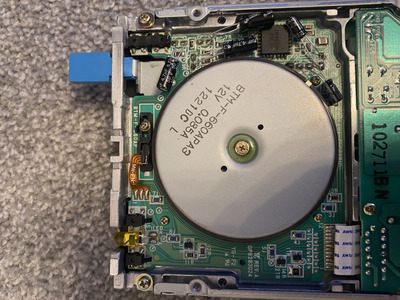
I just recently repaired an ALPS drive (DFP723D33A, 34 pin, media-sense) on my recently acquired model 35SX. It was just a recap and cleaning job, essentially, and now the drive works perfectly.
Couple things to check. Like previous poster said, there might be corrosion from the electrolyte on the traces so it might prevent the drive from working. Another thing to note is that electrolyte is conductive, so if you havent't cleaned that crap from the PCB, it may short some stuff and drive doesn't work because of that.
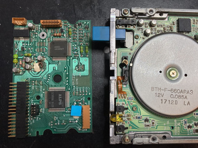
Torn pad isn't necessarily a deal breaker. In fact, I managed to tear one during my recap work due to my mistake: I didn't want to use hot air for desoldering (so much plastic and rubber near the capacitors) so I went with a twisting method and screwed up with one cap. However, it was relatively easy to trace from the pad to the next SMD resistor and I just soldered the new cap to that point. One thing I almost missed before starting the recap is that in my drive there are three bi-polar capacitors on the motor board. "Normal" polarized electrolytic caps won't work there, but this should not affect the head movement at all, naturally. But your drive might be of a different type and there may be bi-polar caps on the control side too, so check that you have used correct caps. If you replaced bi-polar caps with polarized ones, that may cause the problem.
Also, I specifically used electrolytic caps as replacement, like the originals were. Reason is that I wanted to be sure that the drive works after recap 100%. Changing cap type to tantalum or ceramic changes capacitor ESR dramatically to lower value and I have no clue how sensitive that circuit is for ESR. So, to be sure that circuit still has 100% identical specs after recapping, I went with electrolytic caps.
One thing worth checking is the possible ribbon/flat flex cables. They might have fractures and that might be the reason why yours isn't working.