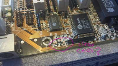
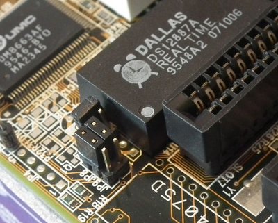
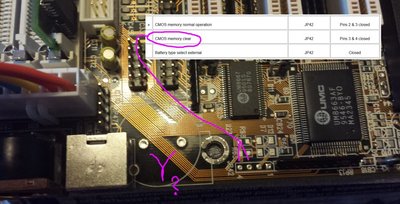
Opiate: You are attempting to short the wrong two solder pads for clearing the CMOS. The implementation of JP42 was for one possible design of this board which incorporated the CR2032 battery and a different clock module. All the MB-8433UUD boards I have seen, which include the first version all the way to the last version (v3.1) have a Dallas/ODIN Real-Time Clock module, which has an integrated battery. You should be setting the JP12 jumper to 3-4 to clear the CMOS. Then open the jumper to return to normal operation. Jumper headers 1/2 should be solder pads only. The caveat to this is that some RTC modules do not have the ability to clear the CMOS settings. Such modules are those which do NOT contain an A suffix, e.g. DS12887+ or DS12887, or DS1287. I am pretty sure that most of these boards were outfitted with an A-type RTC, usually an ODIN OEC12C887A, which allows for clearing the CMOS data preferences.
I have seen this board get hung-up on some PCI cards, whereby only a clearing of the CMOS was able to resolve. For those boards without the A-type RTC, you might need to desolder your RTC and replace it, or wait a few more years for the battery to no longer hold charge.
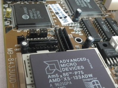
You mentioned earlier about a GeForce2. This board will work with a GeForce2 MX400 if you are using an Am5x86 or Pentium Overdrive. I could not find any functioning drivers for such card if you are using a Cyrix/IBM 5x86. If you decide you want to try a GF2, use NVIDIA Detonator drivers v12.41 w/Am5x86. If using a POD, newer drives up to 77.72 will work.
You mentioned that JP17 is missing the header. I've seen this happen on the older version 2.0 boards. Newer version 2.0 boards have the jumper header in place. I'm not sure why they didn't change the PCB revision. The newer version 2.0 boards are a lot similar to the early 3.0 boards. Having JP17 soldered closed means that you cannot use FSBs of 20, 50, 60, and 83 MHz, but 25, 33, 40, and 66 MHz are available to you.
Concerning your intermittent PCI video issue (I realise it is no longer intermittent, it doesn't work at all), I wonder if your crystal is failing. It would be helpful to probe the PCI clock with an oscilloscope. I suppose your PLL could also be failing, which on this board is socketed and easy to replace. I have had issues on my version 1 board, which did not allow me to run the PCI bus at 1:1 (CMOS setting), even with a 33 MHz BUS. From that experience, I just avoid version 1 boards. Version 1 boards don't have any version numbers printed on them.
Also, this board works best with FPM memory. And if you are trying to use a CF card with the onboard IDE, I find that you need to set IDE Primary Master PIO to PIO-4, not AUTO.
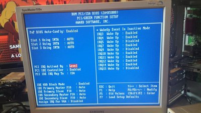
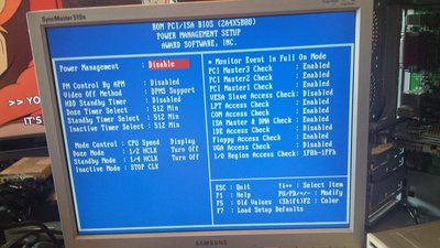
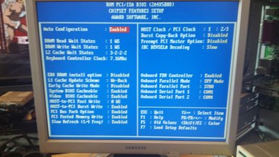
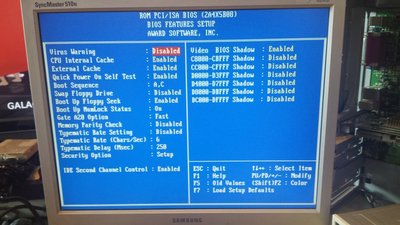
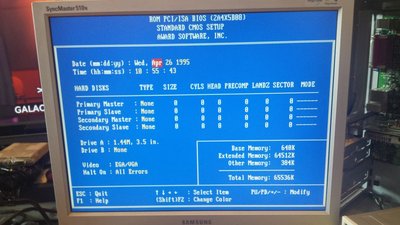
I have looked over your BIOS settings. I will point out some of the differences from what I usually set.
PCI IDE IRQ Map To : PCI-AUTO
IDE Primary Master PIO - AUTO, if using CF card, set to PIO-4.
DRAM Read/Write = 0WS if using 40 MHz FSB or less. (Note my RAM is 60 ns or better)
L2 cache wait states = 2-1-1-1 if using 40 MHz or less and 256 KB of double-banked cache. (Note my cache is 15 ns or better)
Early Cache Write Mode = Enabled
Burst Copy Option = Enabled
What BIOS revision are you using? You might want to consider updating it. Updating the BIOS will also reset the ESCD, which may help with some PCI/ISA configuration problems.
Plan your life wisely, you'll be dead before you know it.


