Reply 40 of 105, by shamino

- Rank
- l33t
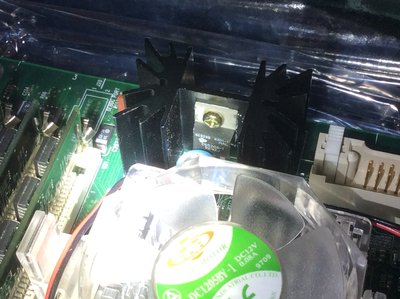
Intel had a specification for removable voltage regulator modules that go into sockets like that. They were most common on higher end Pentium Pro and P2 era boards, and most especially with boards that supported multiple CPUs. The latest board I've seen them on were some Dell GX150 P3 Coppermine boards (but later GX150 boards have it soldered permanently instead). I've never seen them on a socket-7 before your picture.
Those VRMs were identified by a revision, but I don't remember what revision corresponds to what generation of CPUs anymore. I've had a little experience using those things but not enough to be certain of how interchangeable they are.
Since it's a socket-7 Pentium board it might be the earliest generation there is of those removable modules. I'm not sure if there's any danger posed by using a VRM that's too new. One issue that I think does have to be considered is that I've seen those VRMs labeled based on what input voltage they expect (all mine say 5v on them). If the input voltage didn't match I'm sure bad things would happen. Lacking any documentation, you'd have to use a multimeter to figure out what input voltage is going to that socket, or given how close it is to the ATX power connector it might be possible to eyeball it.
It's possible the VRM isn't for the CPU but is instead for the onboard cache memory, but I think that's less likely. Some boards had multiple VRM sockets, one for each CPU and one for powering their cache.
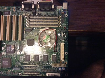
There seems to be an onboard linear voltage regulator sitting near the CPU, plus the removable VRM (currently missing). So it's a little confusing what's doing what here. It uses an ATX power supply so it shouldn't need an onboard 3.3v regulator. I'm guessing the removable VRM is for the CPU power, and the onboard regulator is for something else, but not sure what. The only way to figure out the scheme for sure would be to poke around with a multimeter.