VOGONS


Reply 20 of 29, by Paadam

User metadata
Rank Member
Rank
Member

It actually did not make any difference whether I used the AUX 3.3v connector or not. And note that I only had stability issues when running at 133 MHz FSB, it is most likely rock stable at lower speeds.
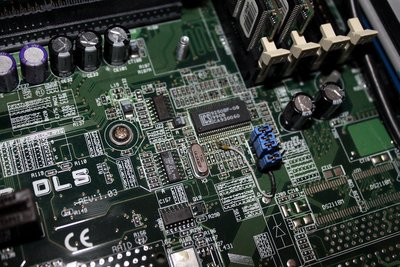
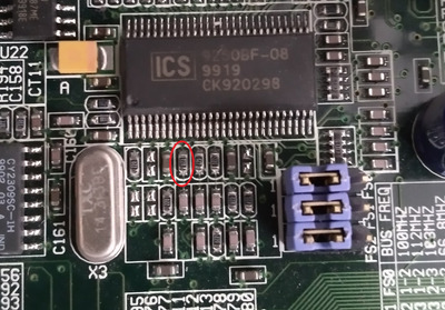
Problem with XG-DLS is that it does not have oboard 3.3v regulation unlike most BX boards fr example. It has HIP6018BCB instead if more common HIP6019BCB (which is used on P2B-DS and many other boards and has 3.3v regulation) and thus it cannot compensate for different VIO voltages. But there's nothing that some tinkering wouldn't fix 😉

kixs wrote:

It's good to see the board got into the right hands... You certainly know your way with hardware hacks 😀

Meanwhile 486 boards are still waiting for some spare time 🙁

Thanks man! But at least you can be sure that the boards work, I tested them 😀

Many 3Dfx and Pentium III-S stuff.
My amibay FS thread: www.amibay.com/showthread.php?88030-Man ... -370-dual)

Reply 21 of 29, by luckybob

User metadata
Rank l33t
Rank
l33t

Well, considering voltage regulation is on the CPU, i'm not surprised. I guess asus did not plan on people really overclocking STUPIDLY EXPENSIVE hardware.

It is a mistake to think you can solve any major problems just with potatoes.

Reply 22 of 29, by Paadam

User metadata
Rank Member
Rank
Member

It's most likely due to cost considerations, it's always cut where you can, even on high cost products (be it computer parts, cars, you name it).

They could have easily used HIP6019BCB which only differs from HIP6018BCB in that it has additional vOUT for 3.3v but did not do that. All other functions are the same. And XG-DLS still has dual VRM's for both CPU's based on HIP6004B (VID's still work because Drake, Tanner and Cascades all have different voltage requirements (and earlier ones had separate voltage for L2).

Many 3Dfx and Pentium III-S stuff.
My amibay FS thread: www.amibay.com/showthread.php?88030-Man ... -370-dual)

Reply 23 of 29, by m1919

User metadata
Rank Member
Rank
Member
Paadam wrote:

Did the 4th FSB jumper mod to XG-DLS. It's PLL fully supports 133/33 operation but Asus omitted FS3 jumper for some reason which means 133MHz was only possible with PCI at 44 MHz (totally unacceptable). Soldered a jumper header with center pin going to PLL pin 9 through 10k resistor, now it works perfectly. And since Xeons have multipliers unlocked to lower ones (like some Pentium MMX), I just set multi to 5.5 and set FSB to 133 MHz, now my 700/100/1M works at 733/133/1M 😀 Next is to get the 5/12v Xeons working at 2.8v board, already dug through datasheets and OCVR's (on-board voltage regulators) seem to be different between the types. At first I though it was usual Intel stuff (playing with RESET# pins, HV_EN etc) but seems that it requires OCVR swap (there's two of them), CPU change itself (BGA rework) or just separate VCC_CORE pins from CPU and feed it with 5v supply (5/12v works with either). Will test the CPU's with my Dell Precision 620 board, don't want to risk at all with Asus one 😀

I approve of this thread.

Can I get some better shots of the jumper mod you did to get 133/33MHz functionality? Also what are the jumper settings for that?

Now also you have mentioned this board does not regulate 3.3v to the procs, but instead relies directly on 3.3v rail from the PSU. I've had some instability issues on my own XG-DLS boards; are there any modern PSUs that have a strong 3.3v rail?

Crimson Tide - EVGA 1000P2; ASUS Z10PE-D8 WS; 2x E5-2697 v3 14C 3.8 GHz on all cores (All core hack); 64GB Samsung DDR4-2133 ECC
EVGA 1080 Ti FTW3; EVGA 750 Ti SC; Sound Blaster Z

Reply 24 of 29, by Paadam

User metadata
Rank Member
Rank
Member

Here's better photo of the jumper mod. All jumpers must be in 1-2 position for 133/33 mode.
I just took 3pin jumper header, bent center pin to one direction and outer pins to opposite direction, removed the plastic cover on XG-DLS jumpers, soldered the outer jumpers to XG-DLS jumper and routed a thin wire from center jumper to PLL through 10k SMD resistor. Took maybe 30 minutes total.

Attachments

  • XG-DLS_133_3.jpg
    Filename
    XG-DLS_133_3.jpg
    File size
    305.6 KiB
    Views
    943 views
    File license
    Fair use/fair dealing exception

Many 3Dfx and Pentium III-S stuff.
My amibay FS thread: www.amibay.com/showthread.php?88030-Man ... -370-dual)

Reply 25 of 29, by Paadam

User metadata
Rank Member
Rank
Member

Struggled with XP Pro install onto my DPT SCSI RAID card with two 10k rpm at RAID0, it would hang at "Setup is starting Windows". Digged around and pushed F5 during text mode setup to set HAL manually to ACPI Multiprocessor PC, still hang, then "MPS Multiprocessor PC" and it would install fine. Googling around revealed a bug, both hardware and software bug regarding Asus boards: https://eu-rma.asus.com/support/faq/faq075_W2 … CPI_dual-mb.htm I used google translate for the page.

Haven't yet resoldered the resistor and I am not sure if it helps but I hope so (kinda annoying to turn the computer manually off and having something that doesn't work). ACPI worked just fine with single CPU installed.
Any other XG-DLS user knew about this?

Many 3Dfx and Pentium III-S stuff.
My amibay FS thread: www.amibay.com/showthread.php?88030-Man ... -370-dual)

Reply 27 of 29, by Paadam

User metadata
Rank Member
Rank
Member

Did the resistor mod, now installed XP with "ACPI Multiprocessor PC" HAL without a hitch! Applies to Windows 2000 also according to the Asus website.

Many 3Dfx and Pentium III-S stuff.
My amibay FS thread: www.amibay.com/showthread.php?88030-Man ... -370-dual)

Reply 28 of 29, by MadYoshi

User metadata
Rank Newbie
Rank
Newbie
Paadam wrote on 2016-11-30, 09:17:

Here's better photo of the jumper mod. All jumpers must be in 1-2 position for 133/33 mode.
I just took 3pin jumper header, bent center pin to one direction and outer pins to opposite direction, removed the plastic cover on XG-DLS jumpers, soldered the outer jumpers to XG-DLS jumper and routed a thin wire from center jumper to PLL through 10k SMD resistor. Took maybe 30 minutes total.

Hallo Paadam,

it is possible that you can take a picture in a more high resolution?
In my photo I have marked the place where you soldered the wire. Is that the right place?
There is already a resistor, I assume I have to replace it with the 10k SMD resistor. Right?

FSB.jpg
Filename
FSB.jpg
File size
546.42 KiB
Views
552 views
File license
Fair use/fair dealing exception