VOGONS


First post, by devius

User metadata
Rank Oldbie
Rank
Oldbie

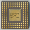
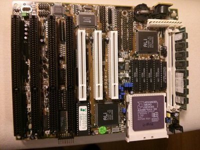
I've got a non-booting Socket 3 motherboard over here. It's one of those tiny late 486 boards with the Ali 1489/1487 chipset and an AMD Am486DX4-100:

IMG_20170221_211943.jpg
Filename
IMG_20170221_211943.jpg
File size
289.96 KiB
Views
751 views
File license
Fair use/fair dealing exception

The problem is that it doesn't boot. I've analyzed it the best that I can but I'm not sure what to do next. Here's what I found out:

  • All other components work properly, only the motherboard itself doesn't
  • With CPU, RAM, video card connected to monitor and a boot analyzer card attached to the parallel port the analyzer will briefly flash when turning on the system, but then turn off all LEDs
  • If I disconnect the monitor cable but leave everything else in place the analyzer will then show some boot codes and all LEDs will remain lit when I turn the system on, but it will not actually boot
  • The voltage regulator outputs only 1,8V instead of the expected ~3,45V as it's configured to do
  • If I take out the CPU the voltage regulator outputs the expected ~3,45V
  • Both the base and the collector of the TIP107 output transistor of the voltage regulation circuit show the same 1,8V voltage, but I'm almost certain there should be a difference
  • There doesn't seem to be any blown components or cut tracks, although one of the tracks that connects power directly from the PSU connector to the ISA slots appeared to be a bit burnt in a spot, but it was only superficial, with the copper trace itself in good working order

This seems to point to some kind of problem with the CPU socket, or maybe the voltage regulation circuit, although I find it strange that it works properly without a CPU attached. Note that the CPU is verified to work correctly, and I also tried other similar CPUs and the result is the same. The voltage regulator is composed of a TL431 and two transistors, a 2N3904 and the aforementioned TIP107.

Here's a closeup of the regulator:

IMG_20170221_212013.jpg
Filename
IMG_20170221_212013.jpg
File size
143.11 KiB
Views
751 views
File license
Fair use/fair dealing exception

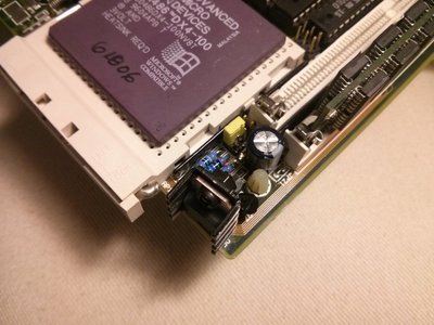
Any ideas? Should I just go ahead and replace the regulator components? They should be easy to source.

Last edited by devius on 2017-02-22, 18:37. Edited 1 time in total.

Reply 1 of 8, by Robin4

User metadata
Rank l33t
Rank
l33t

First you need to be 100 % sure that all jumpers are set correctly (this is a most common not- bootable problem or no screen)

Second thing you could do is swap out the bios rom with a new programmed one..

~ At least it can do black and white~

Reply 2 of 8, by Tetrium

User metadata
Rank l33t++
Rank
l33t++

Do you have another CPU to try? I prefer to use some common 5V chip.
I'd take Robin4's advice as good advice though as he knows more about this stuff than I do 😁

Whats missing in your collections?
My retro rigs (old topic)
Interesting Vogons threads (links to Vogonswiki)
Report spammers here!

Reply 3 of 8, by devius

User metadata
Rank Oldbie
Rank
Oldbie

I'm 100% sure that all jumpers are set correctly, because I have another extremely similar board and the exact same jumper settings work correctly on that board. I also tried another DX4-100 CPU, but not any 5V CPU. I'll try that next.

I could swap out the BIOS chip, but are you sure a defective BIOS could cause the voltage regulator to output a much lower voltage with a CPU attached, but the correct voltage without one?

Reply 4 of 8, by Retromania

User metadata
Rank Newbie
Rank
Newbie

BTW does anyone have the manual for this motherboard model? (Jetway J-426B)

Ive only found this one:
http://motherboards.mbarron.net/models/486pci/ts486.htm

...But my jumpers layout is completely different, maybe its a early or later revision 😐

www.retromania.pt

Reply 5 of 8, by Tetrium

User metadata
Rank l33t++
Rank
l33t++

That board does look familiar somehow. It is most likely a (very) late 486 board. I couldn't find any match on th99 though. It looks similar to syl8884 but it is not the same. Also the overhanging CPU socket looks familiar to me, but I can't remember exactly where I've seen it before.

Devius, could you please mention all marking on the back of the board and all silkscreened bits of information on the front? Often jumper settings are silkscreened on the board, but perhaps it's a good idea to take a couple more detailed pics of every bush of jumpers and everything silkscreened on the board.

Oftentimes several manufacturers used one basic layout which were different in name and (alas) also jumper settings.

I'd still recommend trying out a 5v CPU as that way any potential problems with the voltage regulator can be ruled out.

Whats missing in your collections?
My retro rigs (old topic)
Interesting Vogons threads (links to Vogonswiki)
Report spammers here!

Reply 6 of 8, by devius

User metadata
Rank Oldbie
Rank
Oldbie
Tetrium wrote:

That board does look familiar somehow. It is most likely a (very) late 486 board.

Yes it is. This one is from December 1995.

Tetrium wrote:

I couldn't find any match on th99 though.

The one Retromania linked to is extremely similar. The only difference is the placement of JP11 and the front panel connectors that are completely different.

Tetrium wrote:

Devius, could you please mention all marking on the back of the board and all silkscreened bits of information on the front? Often jumper settings are silkscreened on the board

Sure, but there are no jumper settings at all on the silkscreen in this case. The board barely has room for the components let alone instructions 🤣

On the back it only says: "TMF M21 94V-0" and a date code of "9540". No other letters or numbers. On the front: "T.W. J-426B". Everything else is component names.

Tetrium wrote:

Oftentimes several manufacturers used one basic layout which were different in name and (alas) also jumper settings.

At this point I'm almost certain the jumpers are correctly configured because...

Tetrium wrote:

I'd still recommend trying out a 5v CPU as that way any potential problems with the voltage regulator can be ruled out.

I did try that and the voltage was also way lower than it was supposed to. With no CPU attached it reads 4,66V, and with a CPU it drops to ~2,45V" so it is almost certainly a regulator problem. I just don't know what. The resistors measure fine but I don't know if the lone regulator output capacitor could cause this problem. It looks like the regulator can't keep up with the necessary current demand, but nothing gets hot, so I'm almost certain it's not a short. I measured around looking for shorts and can't find any.

At this point I think I'm going to try the shotgun approach and start replacing some components in the hopes that one of the easily replaceable ones is the cause.

Reply 7 of 8, by creepingnet

User metadata
Rank Oldbie
Rank
Oldbie

Based on going through the very same stuff as you this week upgrading my FIC 486-PVT motherboard, you might want to look around for alternate jumper settings for the same chip.

Originally, the 486 PVT I had had the jumpers for an AM486DX4-100 to be RN18 populated and RN17, 16, and 19 empty, and the voltage set for 3 volts. The revised jumper settings called for RN17 and RN19 populated - I could not get my new AM486DX4 to boot until I fixed that issue.

Speaking of which, you MIGHT want to change the voltage to 3.0v if the board support it. Reason being, those AM486DX4 chips (yours included) are marked for 3.0 Volts. My FIC supports 3.0 volts (CN6 = Jumpers 7&8 and 9&10 shorted, and JCV1 jumpered to pins 1&2). Those AMD 486DX4 CPU chips seem extremely finicky about jumper settings and if there's so much as one thing off it won't POST because they either know or put some kind of lockout on it.

Another thing to try is the Diagnostic card to make sure it's even making it to the IRDY (Device Ready) stage of boot which is one of the last stages before the video adapter kicks in and starts showing POST messages.

~The Creeping Network~
My Youtube Channel - https://www.youtube.com/creepingnet
Creepingnet's World - https://creepingnet.neocities.org/
The Creeping Network Repo - https://www.geocities.ws/creepingnet2019/

Reply 8 of 8, by devius

User metadata
Rank Oldbie
Rank
Oldbie

Fixed it!

It was the TIP107C transistor that was malfunctioning somehow. What threw me off was that it wasn't shorted between Emitter and Base, even though those two pins had the same voltage, when there should have been a difference.