VOGONS


First post, by popeyewinter

User metadata
Rank Newbie
Rank
Newbie

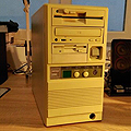
I recently bought a 486 machine from a guy and it works perfectly, only problem is the turbo button, as well as the LED light and speed display for it does not work.

even though this is not crucial, it would be cool to get it working. I am hoping it's just wired incorrectly.

I am having trouble finding out how to wire it properly, I tried trial and error and got nothing.

I am googling but haven't found anything, I used a utility and found this info out, any help would be appreciated:

Chipset Info: 85C496/497 486 PCI Chipset […]
Show full quote

Chipset Info: 85C496/497 486 PCI Chipset

BIOS DATE: 03/14/96

Award Modular BIOS V4.50G

Award ID-String: 03/14/96-SiS-496-497/A/B-2A4IBL13C-00

Board/BIOS-Version: 96/3/14

OEM: LUCKY STAR

Chipset: SiS-496-497/A/B //SiS 496/497

Reply 2 of 17, by Robin4

User metadata
Rank l33t
Rank
l33t

The color of the wire is mostly the positive side.. The white wire is the negative side.. It could be possible that the leds are just worn out.. Maybe its better to test those first, so you know they are working fine..
Then have to look on the motherboard where to connect them to.

~ At least it can do black and white~

Reply 4 of 17, by popeyewinter

User metadata
Rank Newbie
Rank
Newbie
Robin4 wrote:

The color of the wire is mostly the positive side.. The white wire is the negative side.. It could be possible that the leds are just worn out.. Maybe its better to test those first, so you know they are working fine..
Then have to look on the motherboard where to connect them to.

This may sound funny, but what are leads?

How should I test them?

Reply 5 of 17, by SSTV2

User metadata
Rank Oldbie
Rank
Oldbie

Have you at least downloaded the manual from second link? It says that CN13 is for turbo switch, a two-pin header and CN14 is for turbo LED (switch state indication). If your 7 segment LED display is not lit, it probably means that it's not connected to a 5V rail, AT PSUs have a 2pin connector dedicated just for that display, check if it's connected. Turbo switch should be connected between MB and 7 segment display also.

Reply 6 of 17, by popeyewinter

User metadata
Rank Newbie
Rank
Newbie
SSTV2 wrote:

Have you at least downloaded the manual from second link? It says that CN13 is for turbo switch, a two-pin header and CN14 is for turbo LED (switch state indication). If your 7 segment LED display is not lit, it probably means that it's not connected to a 5V rail, AT PSUs have a 2pin connector dedicated just for that display, check if it's connected. Turbo switch should be connected between MB and 7 segment display also.

No, but I will, and will try it tomorrow.

the light for power, and the hard disk do light up, so I guess that the LED itself is okay.

Reply 7 of 17, by popeyewinter

User metadata
Rank Newbie
Rank
Newbie

actually, I just looked at the maunal: http://motherboards.mbarron.net/models/486pci/ls486ec2.jpg

it seems to be incorrect as CN14 is where I currently have the power LED connected and it works. It didn't work anywhere else I tried it.

Reply 8 of 17, by SSTV2

User metadata
Rank Oldbie
Rank
Oldbie
popeyewinter wrote:

t seems to be incorrect as CN14 is where I currently have the power LED connected and it works. It didn't work anywhere else I tried it.

Power LED header is in 5pin "keylock" section, google it, it's standard for all desktop PCs of that time and if your green power LED is lit now then turbo switch is on for sure 😀

Reply 9 of 17, by popeyewinter

User metadata
Rank Newbie
Rank
Newbie
SSTV2 wrote:
popeyewinter wrote:

t seems to be incorrect as CN14 is where I currently have the power LED connected and it works. It didn't work anywhere else I tried it.

Power LED header is in 5pin "keylock" section, google it, it's standard for all desktop PCs of that time and if your green power LED is lit now then turbo switch is on for sure 😀

ummm, on mine the 5 pin section is actually where cn13 and cn14 are....

I will post a picture tomorrow.

Wait are you implying to put the Turbo SW into the same section as the power LED?

Reply 10 of 17, by popeyewinter

User metadata
Rank Newbie
Rank
Newbie

So, I made some progress through some more trial and error, the turbo button works now, however the led still doesn't display the speed.

18010756_10209281767585389_5917449507447214988_n.jpg?oh=79459194340eb5aefc0d03353b369612&oe=5984A752

The green light is the power, the orange is turbo, the one at the bottom is the HDD and it works, but only lights up read when their is activity with the hard disk.

the big black space is where the processor speed should be... https://scontent-ort2-1.xx.fbcdn.net/v/t1.0-9 … 612&oe=5984A752...

Judging by the following pictures, I think I am missing the led board that displays the speed, as the black space seems to just be a window:

18010150_10209281785425835_8961301574810211890_n.jpg?oh=60fafcf02e7ee4189cdd4f12d7a9a442&oe=598039F4

Reply 13 of 17, by popeyewinter

User metadata
Rank Newbie
Rank
Newbie

It is with great sadness that I must announce the death of my Turbo button, while working on it, the button itself got stuck, and I cannot seem to get it properly unstuck.

While testing I didn't see any smoke coming or anything when I was pushing it previous to it getting stuck, but none the less, I have disconnected the "Turbo SW" wire and only left the "Turbo LED" wire connected to light up that small circle beside where it says "turbo".

R.I.P Turbo Button.

P.S: I guess "R.I.P Turbo Button" is better than "R.I.P Motherboard"...

Reply 14 of 17, by kanecvr

User metadata
Rank Oldbie
Rank
Oldbie

OP, the MHz display is nothing fancy - the display is configured by use of the jumpers behind it to show whatever you want it to, irregardless of actual CPU speed. It does not communicate with the motherboard in any way. It has one power lead (5V) with 2 pins that comes straight from the PSU - usually a small red / black 2 pin wire - and a 3 pin connector that goes to the turbo button. When you push the turbo button on the case the MHz display shifts from one row of jumpers to another, displaying another "speed".

I'm 100% sure your MHZ display is not getting power from the PSU. The 2 pin cable is either not connected, or connected incorrectly to it. Find said cable in the case, and wire it to the only seperate 2 pins on the MHZ display's PCB, and it should work.

Reply 15 of 17, by brostenen

User metadata
Rank l33t++
Rank
l33t++
kanecvr wrote:

I'm 100% sure your MHZ display is not getting power from the PSU.

That's 100% correct. Nothing fancy about that. 😀 Every 5volt source can be used.

Don't eat stuff off a 15 year old never cleaned cpu cooler.
Those cakes make you sick....

My blog: http://to9xct.blogspot.dk
My YouTube: https://www.youtube.com/user/brostenen

001100 010010 011110 100001 101101 110011

Reply 16 of 17, by popeyewinter

User metadata
Rank Newbie
Rank
Newbie
kanecvr wrote:

OP, the MHz display is nothing fancy - the display is configured by use of the jumpers behind it to show whatever you want it to, irregardless of actual CPU speed. It does not communicate with the motherboard in any way. It has one power lead (5V) with 2 pins that comes straight from the PSU - usually a small red / black 2 pin wire - and a 3 pin connector that goes to the turbo button. When you push the turbo button on the case the MHz display shifts from one row of jumpers to another, displaying another "speed".

I'm 100% sure your MHZ display is not getting power from the PSU. The 2 pin cable is either not connected, or connected incorrectly to it. Find said cable in the case, and wire it to the only seperate 2 pins on the MHZ display's PCB, and it should work.

So you are saying that there's cables coming from my power supply that I should hook up to the MHZ?

So I know how to fix the display part then.

However, after testing, even when the Turbo SW wire is hooked in, it doesn't seem to actually change the processor speed at all, I tested with both a performance monitoring utility and castle wolfenstein, in both positions the performance utility didn't notice a change in processor speed, and castle wolfenstein was unplayable.

Last edited by popeyewinter on 2017-04-18, 18:49. Edited 1 time in total.

Reply 17 of 17, by brostenen

User metadata
Rank l33t++
Rank
l33t++

If there is two wires carrying 5volt, going out of the PSU, then you can hook them up.
Just measure it with a multimeter first. Or you can just mod a molex connector.
All you need, is to feed that led display 5volt, and were it comes from are not really an issue.

Don't eat stuff off a 15 year old never cleaned cpu cooler.
Those cakes make you sick....

My blog: http://to9xct.blogspot.dk
My YouTube: https://www.youtube.com/user/brostenen

001100 010010 011110 100001 101101 110011