VOGONS


Reply 20 of 85, by Deksor

User metadata
Rank l33t
Rank
l33t

The cache chips used are pretty standard for 486 gears. You can try ISSI IS61C256AH-15N chips for example

As for the JP5 usage, it's described in here in the "memory" category https://www.elhvb.com/mobokive/Archive/PcChip … 7_corrected.zip

Trying to identify old hardware ? Visit The retro web - Project's thread The Retro Web project - a stason.org/TH99 alternative

Reply 21 of 85, by Nexxen

User metadata
Rank Oldbie
Rank
Oldbie

@Deksor
Still need help.

Do you have any suggestion on "where" to find that kind of chips?
I really have no clue. I can put up to 1024kb, why not trying for the top.
Thanks in advance

PC#1 Pentium 233 MMX - 98SE
PC#2 PIII-1Ghz - 98SE/W2K

Reply 22 of 85, by Deksor

User metadata
Rank l33t
Rank
l33t

Try eBay. Beware of fake chips though. 1MB is going to be costly and won't bring you much though, 256KB is plenty enough.

Trying to identify old hardware ? Visit The retro web - Project's thread The Retro Web project - a stason.org/TH99 alternative

Reply 23 of 85, by Nexxen

User metadata
Rank Oldbie
Rank
Oldbie

Thanks for the advice.
Old stuff costs I guess 😀

So, there's a seller from Germany. I'm gonna go with that guy. 2.40€ a piece of the very same model you suggested.

PC#1 Pentium 233 MMX - 98SE
PC#2 PIII-1Ghz - 98SE/W2K

Reply 24 of 85, by ykot

User metadata
Rank Newbie
Rank
Newbie

I have this exact revision of the board with real cache and it works just fine. In terms of functionality, I think it is a pretty good board - mine seems to work fine with EDO memory and newer Am5x86 processors.

Deksor wrote on 2017-07-05, 11:24:

The only board that had traces getting nowhere I can think of is the M919. No revisions of that board ever had cache while some M912 and some M915i had real cache at some point.

Actually, I have PC Chips M919 too and it has a special proprietary cache slot, for which luckily I had a 256k write-back cache module among my old stuff, and the cache seems to be working fine. It also supports EDO memory and is running with my IBM/Cyrix 5x86 100Mhz processor. So I can confirm that some revisions of M919 do have cache also. 😀

Edit: although from the photo on this page, the board does seem to have two unpopulated slots apparently for some kind of cache, maybe these are the ones that have traces going nowhere.

Reply 25 of 85, by Deksor

User metadata
Rank l33t
Rank
l33t

Well I was wrong when I wrote that (an early version of the m919 has cache slots) however the one in your picture is the later model which has NO cache whatsoever, and the "empty slots" are indeed having the traces getting nowhere.

Trying to identify old hardware ? Visit The retro web - Project's thread The Retro Web project - a stason.org/TH99 alternative

Reply 26 of 85, by Nexxen

User metadata
Rank Oldbie
Rank
Oldbie
ykot wrote on 2020-08-06, 15:36:
I have this exact revision of the board with real cache and it works just fine. In terms of functionality, I think it is a prett […]
Show full quote

I have this exact revision of the board with real cache and it works just fine. In terms of functionality, I think it is a pretty good board - mine seems to work fine with EDO memory and newer Am5x86 processors.

Deksor wrote on 2017-07-05, 11:24:

The only board that had traces getting nowhere I can think of is the M919. No revisions of that board ever had cache while some M912 and some M915i had real cache at some point.

Actually, I have PC Chips M919 too and it has a special proprietary cache slot, for which luckily I had a 256k write-back cache module among my old stuff, and the cache seems to be working fine. It also supports EDO memory and is running with my IBM/Cyrix 5x86 100Mhz processor. So I can confirm that some revisions of M919 do have cache also. 😀

Edit: although from the photo on this page, the board does seem to have two unpopulated slots apparently for some kind of cache, maybe these are the ones that have traces going nowhere.

Could you please post a high res pic of both sides of your M912?
I need a working M912 to check if all the traces that need to be there are actually there 😀

Gracias de antemano.

PC#1 Pentium 233 MMX - 98SE
PC#2 PIII-1Ghz - 98SE/W2K

Reply 27 of 85, by Deksor

User metadata
Rank l33t
Rank
l33t

Just take a voltmeter and check if there's voltage on the pins 😀
If there's a voltage, the traces are connected because it wouldn't make any senses to have the power rails connected and nothing else ^^

Trying to identify old hardware ? Visit The retro web - Project's thread The Retro Web project - a stason.org/TH99 alternative

Reply 28 of 85, by Horun

User metadata
Rank l33t++
Rank
l33t++

I have a few 912, some with white some with black ISA slots, versions 1.4 and 1.7. All have real cache but not sure if pictures would be of much help as they each have diff real cache chips from different manufactures. Now the 919 is a different bugger and think near all had fake cache/no cache (unless you could find the COAST module which is specific to that board and no other will work)

added:

Nexxen wrote on 2020-08-08, 18:14:

Could you please post a high res pic of both sides of your M912?
I need a working M912 to check if all the traces that need to be there are actually there 😀
Gracias de antemano.

You post pics of your board and I will post pics of mine.

Hate posting a reply and then have to edit it because it made no sense 😁 First computer was an IBM 3270 workstation with CGA monitor. Stuff: https://archive.org/details/@horun

Reply 29 of 85, by Nexxen

User metadata
Rank Oldbie
Rank
Oldbie
Horun wrote on 2020-08-09, 02:58:

You post pics of your board and I will post pics of mine.

🤣 Ok!

Last edited by Stiletto on 2020-08-12, 02:34. Edited 1 time in total.

PC#1 Pentium 233 MMX - 98SE
PC#2 PIII-1Ghz - 98SE/W2K

Reply 30 of 85, by ykot

User metadata
Rank Newbie
Rank
Newbie
Nexxen wrote on 2020-08-08, 18:14:

Could you please post a high res pic of both sides of your M912?

I have attached photos of both sides, had to downscale them to 50% due to 2Mb attachment limit. Let me know if you need photos of some specific sections. I am not using this motherboard currently, but as far as I recall, it is jumpered for an AMD DX4 100Mhz W/B.

Attachments

  • mb_cache.jpg
    Filename
    mb_cache.jpg
    File size
    695.82 KiB
    Views
    1104 views
    File license
    Public domain
  • mb_back_2.jpg
    Filename
    mb_back_2.jpg
    File size
    1.27 MiB
    Views
    1104 views
    File license
    Public domain
  • mb_front_2.jpg
    Filename
    mb_front_2.jpg
    File size
    1.12 MiB
    Views
    1104 views
    File license
    Public domain

Reply 32 of 85, by Horun

User metadata
Rank l33t++
Rank
l33t++

Actually the white ISA slot versus black ISA slot should be exact same as long as the v1.7 is stamped in corner near the PSU connector. Rumor is there were two revision 1.7 but have never seen any real physical differences between them. Not saying there were not differences but personally have not seen them. Some sites lits the 1.7 as the 1.74 but is same as my v1.7 afaik. I have one of each plus a white ISA v1.4 (thought I had a third v1.7 but could be in a machine I didn't docu well, as the boards are numbered 1 and 3 so I must have a 2 🤣). Will post pics in a minute but not sure back of board matters since both mine have cache sockets and real cache.

ykot wrote on 2020-08-11, 22:28:

I have attached photos of both sides..

Yep ! Great pics of the M912 v1.7. Thanks !
added: here is one of mine

Attachments

  • IMG_1261s.jpg
    Filename
    IMG_1261s.jpg
    File size
    854.71 KiB
    Views
    1086 views
    File license
    Fair use/fair dealing exception

Hate posting a reply and then have to edit it because it made no sense 😁 First computer was an IBM 3270 workstation with CGA monitor. Stuff: https://archive.org/details/@horun

Reply 33 of 85, by Nexxen

User metadata
Rank Oldbie
Rank
Oldbie

I was taking pics of mine and reducing size...

I am a little confused, I see 32 pin sockets and 28 pin ram chips or as the one above, one 28 I guess for parity (I really am guessing) and 32 pin chips...
Is there any difference?

Thanks for the pics guys, really appreciated!! Posting mine soon.

Attachments

  • P1180859.JPG
    Filename
    P1180859.JPG
    File size
    1.48 MiB
    Views
    1084 views
    File license
    Fair use/fair dealing exception
  • P1180858.JPG
    Filename
    P1180858.JPG
    File size
    1.64 MiB
    Views
    1084 views
    File license
    Fair use/fair dealing exception
  • P1180857bbb.jpg
    Filename
    P1180857bbb.jpg
    File size
    607.64 KiB
    Views
    1084 views
    File license
    Fair use/fair dealing exception
  • P1180856bbb2.jpg
    Filename
    P1180856bbb2.jpg
    File size
    452.82 KiB
    Views
    1084 views
    File license
    Fair use/fair dealing exception
  • IMG_20200709_125728bbb.jpg
    Filename
    IMG_20200709_125728bbb.jpg
    File size
    616.52 KiB
    Views
    1084 views
    File license
    Fair use/fair dealing exception

PC#1 Pentium 233 MMX - 98SE
PC#2 PIII-1Ghz - 98SE/W2K

Reply 34 of 85, by Nexxen

User metadata
Rank Oldbie
Rank
Oldbie

Yes, I have very bad desoldering skills. I didn't have the gun style station.
I checked continuity and there are jump wires to solder.

PC#1 Pentium 233 MMX - 98SE
PC#2 PIII-1Ghz - 98SE/W2K

Reply 35 of 85, by ykot

User metadata
Rank Newbie
Rank
Newbie
Nexxen wrote on 2020-07-09, 11:13:

There are smd capacitors to solder between banks, I haven't identified them yet, if you know V and µF I'd be glad to have the info.

Indeed from the photos there are few capacitors missing, did you find the required values? In theory, I could try to desolder and measure them on my motherboard, but they are located in difficult to reach locations, soldering them back would be quite a challenge.

Reply 36 of 85, by Nexxen

User metadata
Rank Oldbie
Rank
Oldbie
ykot wrote on 2020-08-12, 15:35:
Nexxen wrote on 2020-07-09, 11:13:

There are smd capacitors to solder between banks, I haven't identified them yet, if you know V and µF I'd be glad to have the info.

Indeed from the photos there are few capacitors missing, did you find the required values? In theory, I could try to desolder and measure them on my motherboard, but they are located in difficult to reach locations, soldering them back would be quite a challenge.

No, I have not been able to find the correct values of those smds. I think it'd be best to desolder one myself as I need to buy a few anyway.

I have zero knowledge on smds and maybe you can get the correct values by using some specific multimeter or just by measures... honestly I have no clue.
Not that I'm in hurry 😀

PC#1 Pentium 233 MMX - 98SE
PC#2 PIII-1Ghz - 98SE/W2K

Reply 37 of 85, by ykot

User metadata
Rank Newbie
Rank
Newbie
Nexxen wrote on 2020-08-12, 16:28:

No, I have not been able to find the correct values of those smds. I think it'd be best to desolder one myself as I need to buy a few anyway.

I have zero knowledge on smds and maybe you can get the correct values by using some specific multimeter or just by measures... honestly I have no clue.
Not that I'm in hurry 😀

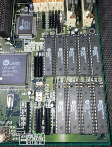
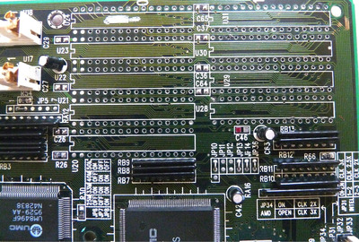
Capacitors cannot be measured in circuit, they would need to be desoldered. I have Weller's solder tweezers for desoldering SMDs, so desoldering is extremely easy, but soldering them back requires traditional approach, which requires either a steady hand or enough space for supporting the solder tip. As I don't have steady hand, I really need some space for support and since these capacitors are located in between cache sockets, there is really zero space and overall it's quite awkward position, so once these capacitors are out, placing them back would be rather difficult. But if no one else has this information, I could try it, for documentation purposes. 😀

For the voltage, these capacitors are likely rated 10-16V and from what it looks like, there could be both filter and bypass capacitors, so my guess would be somewhere from 0.1 to 10 uF range, but I am not an expert on these cache circuits.

Reply 38 of 85, by Nexxen

User metadata
Rank Oldbie
Rank
Oldbie
ykot wrote on 2020-08-12, 18:08:

For the voltage, these capacitors are likely rated 10-16V and from what it looks like, there could be both filter and bypass capacitors, so my guess would be somewhere from 0.1 to 10 uF range, but I am not an expert on these cache circuits.

While checking for continuity I found them to be on the same line.
If I fire up the board, is there any significant measurement I can do for anything? Long shot.

Last edited by Stiletto on 2020-08-16, 05:19. Edited 1 time in total.

PC#1 Pentium 233 MMX - 98SE
PC#2 PIII-1Ghz - 98SE/W2K

Reply 39 of 85, by ykot

User metadata
Rank Newbie
Rank
Newbie
Nexxen wrote on 2020-08-12, 19:21:

If I fire up the board, is there any significant measurement I can do for anything? Long shot.

Can't really tell, but there is a chance the board and cache will work without these capacitors. It would still be a good idea to populate them to reduce the noise and improve system stability.

By the way, you may also want to unsolder JP10-JP36 direct jumpers and put 2x6 headers there so you would be able to configure the cache.