rasz_pl wrote on 2022-12-15, 07:21:
You said earlier you measure while sitting in dos prompt, try while running something CPU intensive in different graphic mode. Doom for example.
Ran DOOM, but peak FFT values remained the same.
rasz_pl wrote on 2022-12-15, 07:21:
you mean just waving probe over the board without connecting to the board? Thats weird, I dont remember seeing it on 5V rail.
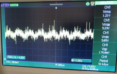
It was there I guess, just not so obvious with 100-200 mV per division. 50 mV /div with x10 prove shows there is something periodic at 5V. With standard x10 probe:
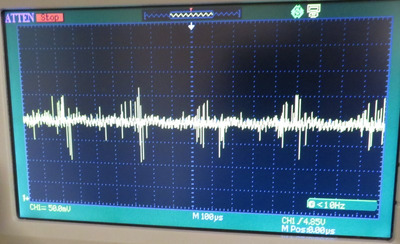
With low inductance probe x10:
rasz_pl wrote on 2022-12-15, 07:21:
you could check what frequency 8253 channel 0 is set at (IRQ 0). Its generating DOS timer interrupt. https://wiki.osdev.org/Programmable_Interval_ … e_Current_Count
Do you have a runable DOS executable? I tried to compile that with my old Borland C++ 5.5 after adding #include <stdio.h>, and int main(void), but the compiler complained of syntax errors. I haven't programmed/compiled with Borland in over 20 years, so I gave up immediately. :)
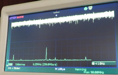
Something that I don't quite understand is the core frequency on 386 systems. The CPU's CLK2 pin shows 80 Mhz and matches the oscillator installed. I see no other frequencies on the scope on CLK2. In the CPU's 1x default mode, 40 MHz, looking at the frequencies observed on VCC3, we see that the 80 MHz freq. has twice the amplitude as the 40 Mhz freq, but the 40 Mhz freq. is still present. :
Where does it come from? Is it actually that all 386's simply half the incoming frequency with onboard PLL and run the system at this halved frequency? Or do regular 386 CPU's merely perform instructions on every other clock signal to make it 40 MHz equivalent, kind of the opposite of DDR memory?
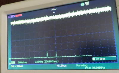
In 2x mode, which is not the default mode on an SXL, we see that 40 MHz signal disappears and the 80 Mhz signal halves, but a 90 MHz signal of the same relative amplitude appears:
What's going on here?
I was also wondering if anyone had any other design suggestions for the PCB? Seems like it might be ready for a second round, assuming the price isn't ridiculous.
What got me thinking was the layers of PCB which don't have ground between them, meaning close signal traces creating cross-talk. I was wondering for these layers if the direction of the traces matters and could be optimised? For example, should the the traces on these planes always be parallel, anti-parallel, or perpendicular? If I recall correctly, when running ethernet cables behind walls and what not, when they cross your mains, they should always cross perpendicular to reduce the interference. I was wondering if such a circumstance would apply to this PCB?
I was also curious if sphere swapped the layers based on rasz's suggestion, or was that undertaking too involved? Or did you think it not beneficial?
Plan your life wisely, you'll be dead before you know it.