VOGONS


Reply 940 of 1193, by feipoa

User metadata
Rank l33t++
Rank
l33t++

Indeed, I think that's why rasz sent a link for something called laser cut 1075 Blue Temper Spring Steel. Ideally any bends would be annealed.

Plan your life wisely, you'll be dead before you know it.

Reply 941 of 1193, by maxtherabbit

User metadata
Rank l33t
Rank
l33t
feipoa wrote on 2023-03-23, 14:54:

Indeed, I think that's why rasz sent a link for something called laser cut 1075 Blue Temper Spring Steel. Ideally any bends would be annealed.

Yeah I'm not doubting the quality of that material, but without a press and stamping die you're still SOL. JLCPCB doesn't do custom stampings 🤣

Reply 942 of 1193, by feipoa

User metadata
Rank l33t++
Rank
l33t++
Best_CPU_removal_tool.JPG
Filename
Best_CPU_removal_tool.JPG
File size
570.96 KiB
Views
847 views
File license
CC-BY-4.0

My preferred removal tool looks to be mostly flat stock. The one tricky section shown can probably be dimpled or braced, if really needed. With the right material, it is probably not necessary.

I find the bends of the other two removal tools excessive.

Plan your life wisely, you'll be dead before you know it.

Reply 943 of 1193, by feipoa

User metadata
Rank l33t++
Rank
l33t++

I should point out that, in reality, I tend to use the flat end of the prybar most of the time because it fits between socket stubs, as shown below. If anyone is going to have anything stamped, you can get way with unbent flat stock for most purposes. I'm not sure of the exact steel composition of this unit, but it is 0.65 mm thick.

Unfortunately, the nubs on the gold male-to-male PGA pins used for the SXL2 assembly are too wide. I don't understand why they are making the nubs so fat. I could not locate units with a smaller diameter in gold, so if anyone locates some, please let me know.

Cyrix_wide_end_of_prybar.JPG
Filename
Cyrix_wide_end_of_prybar.JPG
File size
633.49 KiB
Views
838 views
File license
CC-BY-4.0

Plan your life wisely, you'll be dead before you know it.

Reply 944 of 1193, by Sphere478

User metadata
Rank l33t++
Rank
l33t++

Think pcb would be stiff enough for this?

Sphere's PCB projects.
-
Sphere’s socket 5/7 cpu collection.
-
SUCCESSFUL K6-2+ to K6-3+ Full Cache Enable Mod
-
Tyan S1564S to S1564D single to dual processor conversion (also s1563 and s1562)

Reply 945 of 1193, by maxtherabbit

User metadata
Rank l33t
Rank
l33t
Sphere478 wrote on 2023-03-23, 21:56:

Think pcb would be stiff enough for this?

absolutely not, these things endure a tremendous amount of bending moment

Reply 946 of 1193, by pshipkov

User metadata
Rank Oldbie
Rank
Oldbie

Taking first measurements.

For the adapter with capacitors peak to peak voltage is in the range of ~25mV.

20230326_115216.jpg
Filename
20230326_115216.jpg
File size
619.92 KiB
Views
759 views
File license
Public domain

The one without capacitors - 60mV.

20230326_121811.jpg
Filename
20230326_121811.jpg
File size
589.05 KiB
Views
759 views
File license
Public domain

retro bits and bytes

Reply 947 of 1193, by Sphere478

User metadata
Rank l33t++
Rank
l33t++

Interesting. Wonder why such a difference in reading between feiopa’s and your reading.

Have you guys checked for common mode noise?

Sphere's PCB projects.
-
Sphere’s socket 5/7 cpu collection.
-
SUCCESSFUL K6-2+ to K6-3+ Full Cache Enable Mod
-
Tyan S1564S to S1564D single to dual processor conversion (also s1563 and s1562)

Reply 948 of 1193, by pentiumspeed

User metadata
Rank l33t
Rank
l33t
pshipkov wrote on 2023-03-26, 19:19:
Taking first measurements. […]
Show full quote

Taking first measurements.

For the adapter with capacitors peak to peak voltage is in the range of ~25mV.
20230326_115216.jpg

The one without capacitors - 60mV.
20230326_121811.jpg

MUCH better to have 25mV, 60mV is too much.

Try to parallel one or two 10uF polymer on the 5V plane next to the socket and see? Keep lead short. Experiment is what we do. I do have a scope too but my desk is a mess at this moment. I love to experiment.

You still have low frequency sine wave embedded in the VCC for core. This is vibrating the CPU.

Cheers,

Great Northern aka Canada.

Reply 949 of 1193, by pshipkov

User metadata
Rank Oldbie
Rank
Oldbie

My only CPU is not good enough to go past 80mhz.
I assume at that frequency noise levels are not a major factor.
Only way to tell is to obtain processor that can go to 90 or even 100mhz.
Much bigger chance minor factors start making a difference there.

retro bits and bytes

Reply 950 of 1193, by feipoa

User metadata
Rank l33t++
Rank
l33t++

Could you set your x-axis to 100 uS, y-axis divisions to 50 mV, and do full-screen mode using manual cursor for V p-p? Lots going on in that image. Also, be sure to set your probe to x10 and tell your scope that you are using x10. Are you also able to take a photo of your setup with probe on VRM pins?

Plan your life wisely, you'll be dead before you know it.

Reply 951 of 1193, by feipoa

User metadata
Rank l33t++
Rank
l33t++

Also, set the VRM to 4.05 V output using your DMM. This will offer a more consistent comparison with my results.

Compare your DMM's reading to that of your scope, using like 2 V / div. Compare the DMM's reading with probe's at x1 and x10. Which probe setting is more in agreement? Don't forget to tell your scope if you are using x1 or x10.

Plan your life wisely, you'll be dead before you know it.

Reply 952 of 1193, by rasz_pl

User metadata
Rank l33t
Rank
l33t
pshipkov wrote on 2023-03-26, 19:19:

Taking first measurements.

400mV? did you set scope to 1x and probe to 10x or something?

Open Source AT&T Globalyst/NCR/FIC 486-GAC-2 proprietary Cache Module reproduction

Reply 953 of 1193, by pshipkov

User metadata
Rank Oldbie
Rank
Oldbie

Hmm, it is possible (probe 10x, but oscilloscope at 1x). This setting is buried in the “acquire” menu and i found myself forgetting to set it couple of times, but captured metrics, that i pay attention to, dont get affected much or at all. Thats why i kept forgetting about it in the first place.
I dont have a lot of muscle memory with oscilloscopes.

Will provide few more measurements as Feipoa suggested in his last posts.

retro bits and bytes

Reply 954 of 1193, by rasz_pl

User metadata
Rank l33t
Rank
l33t

>but captured metrics that i pay attention to dont get affected much

other than being 10 too small 😀 so you had 600 and 250mv of noise

Open Source AT&T Globalyst/NCR/FIC 486-GAC-2 proprietary Cache Module reproduction

Reply 956 of 1193, by pshipkov

User metadata
Rank Oldbie
Rank
Oldbie

For the one without capacitors:
"current" measurements vary ~ 400-500 mV

20230327_090947.jpg
Filename
20230327_090947.jpg
File size
547.01 KiB
Views
615 views
File license
Public domain

With capacitors (including the ones on the top, that Feipoa pointed at lastly):
"current" measurements vary ~250-300mV

20230327_090156.jpg
Filename
20230327_090156.jpg
File size
539.62 KiB
Views
615 views
File license
Public domain

retro bits and bytes

Reply 957 of 1193, by rasz_pl

User metadata
Rank l33t
Rank
l33t

When looking at the traces first one had few different frequencies, second one is primarily one. Check in FFT view https://www.youtube.com/watch?v=VSCoAX2aJ2M

Open Source AT&T Globalyst/NCR/FIC 486-GAC-2 proprietary Cache Module reproduction

Reply 958 of 1193, by feipoa

User metadata
Rank l33t++
Rank
l33t++

I'm not familiar with your scope; what does it mean when there's this fainter shadow image above and below the waveform? Just less data points grabbed in these regions, but the points are still valid? My scope is showing all such points as the same visible intensity.

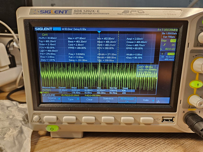
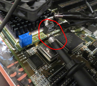
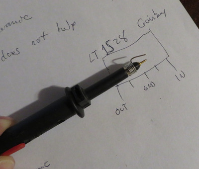
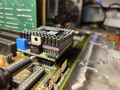
Are you using the low inductance probe, holding it onto the VRM with one hand while the other takes control other scope? From my experience, trying to use the aligator clip ground lead at these low voltage scales introduces more noise. Here is an image I took with it on a different VRM:

Low_inductance_GND_on_x10_probe_1.JPG
Filename
Low_inductance_GND_on_x10_probe_1.JPG
File size
588.36 KiB
Views
589 views
File license
CC-BY-4.0
Low_inductance_GND_on_x10_probe_2.JPG
Filename
Low_inductance_GND_on_x10_probe_2.JPG
File size
398.51 KiB
Views
589 views
File license
CC-BY-4.0

If you are already using the low inductance probe as shown, then something I have noticed is if the ground lead is not quite touching the VRM's GND, you will get this factor of 5 noise amplification on your wave form. When this has happened to me, I moved the probe around, press it in more, etc. until the waveform amplitude looks right. If it still doesn't look right, I pull off the probe and move the GND lead out a bit more so that it sticks out further than the primary probe lead. But before doing any of this, I would set the x-axis and y-axis to where they should be using the clipped-on probe.

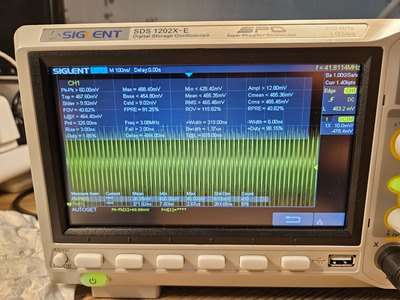
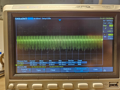
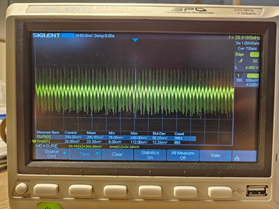
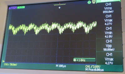
What is the x-axis on your scope set at? Looks like 50 ns/div? Are you measuring the 80 MHz waveform? Could you set your scope to 100 micro-seconds / div? With the MIC29302 regulator, I get something like:

Noise-MIC29302WT.JPG
Filename
Noise-MIC29302WT.JPG
File size
75.37 KiB
Views
589 views
File license
CC-BY-4.0

If we just consider the differential with and without PGA caps, my noise went from 426 mV to 84 mV, so the noise dropped 5x at 5 KHz. I didn't measure noise drop at 80 MHz. From your results, which don't appear to be at 5 KHz, you are seeing from 500 mV to 300 mV, not even 1x drop in noise. Also, that shadowing effect is not occurring on your scope image for the interposer without caps (top side of waveform only). I think the best place to start is setting your x-axis to 100 micro-seconds per division, not 50 nano-seconds.

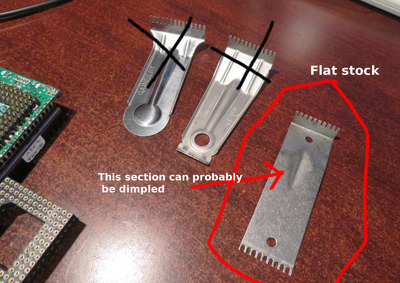
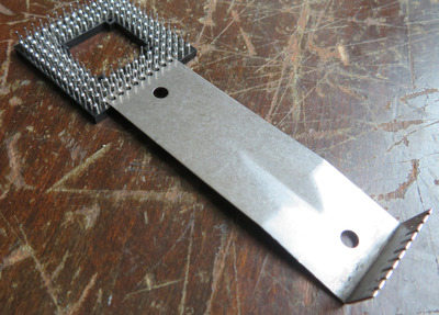
I noticed you decided to solder your PGA caps way down at the base of the PCB. I elected not to do this due to fear of an intermittent short with the wrong plane. I am using 0805 caps soldered at the open air end of the PGA pins to avoid this possible contingency.

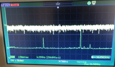
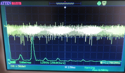
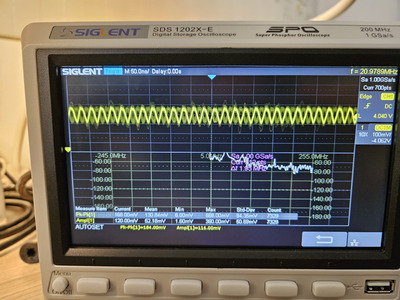
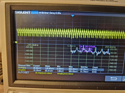
As rasz_pl pointed out, I think checking FFT might be a good idea to see what frequencies are dominant, aside from 60 Hz. I ran two ranges on my setup previously, one in the MHz range, up to around 110 MHz, the other targetting up to around 25 KHz. Hanning position is the position on the centre of the x-axis (centre of scope). My results were:

full bandwidth:
40 MHz: 3.75 Vrms
80 MHz: 7.5 Vrms
90 MHz: 1.75 Vrms

FFT_full_spectrum.JPG
Filename
FFT_full_spectrum.JPG
File size
100.77 KiB
Views
589 views
File license
CC-BY-4.0

low freq:
60 Hz: 25 mVrms
5 KHz: 15 Vrms

FFL_low_freq.JPG
Filename
FFL_low_freq.JPG
File size
95.22 KiB
Views
589 views
File license
CC-BY-4.0

I recall it took quite a fit of fidgeting around with the scales to get the FFT images where I wanted them. I wish there was an auto targetting option on my scope for this. Maybe your newer scope has one.

Plan your life wisely, you'll be dead before you know it.

Reply 959 of 1193, by pshipkov

User metadata
Rank Oldbie
Rank
Oldbie

on Vout with induction probe:

20230327_131815.jpg
Filename
20230327_131815.jpg
File size
1.53 MiB
Views
572 views
File license
Public domain

without capacitors.

20230327_132117.jpg
Filename
20230327_132117.jpg
File size
1.95 MiB
Views
572 views
File license
Public domain

with capacitors:

20230327_131733(0).jpg
Filename
20230327_131733(0).jpg
File size
1.84 MiB
Views
572 views
File license
Public domain

Turned on FFT.
I have good experience programming this stuff, so understand the concept very well, but need to spend time to comprehend what the diagram actually means and how to use the related tools.
For now i turned it on per razs_p request.

Feipoa, will bake the division step adjustment later today, as you requested.

I know what you mean about leaving the caps on the surface. thats why mentioned that surface coating chips off easily, because it did neqrby one of them on a test job with another one of the pcbs.
had to be very careful to the very end.

retro bits and bytes