VOGONS


First post, by GabrielKnight123

User metadata
Rank Oldbie
Rank
Oldbie

I have a 486 motherboard that I have to put jumpers right for its new CPU but when I look at these 3 jumpers with 3 pins each I cant figure out which ones are pin 1 for each, I have some pictures here of the motherboard with the jumpers:

http://s836.photobucket.com/user/sierragames/ … y/486%20Jumpers

I have a manual from the net here:

http://pcrebuilding.altervista.org/9/download … b-486unp301.pdf

but it is not the same exactly as mine for JP34/JP35/JP36 in the manual they only have two pins and on my mobo they have 3 pins and are in a different location.
I spose I could unsolder the pins to look under them to see if I can find the small box out of the 3 pins to find pin 1 but I would rather not solder them out at this stage.
Reply 1 of 2, by GabrielKnight123

User metadata
Rank Oldbie
Rank
Oldbie

I have two more pictures of under the board and I see there are 2 circles and one square for each of the jumpers so would each of the square ones be + or pin one?

http://s836.photobucket.com/user/sierragames/ … y/486%20Jumpers

Reply 2 of 2, by lazibayer

User metadata
Rank Oldbie
Rank
Oldbie

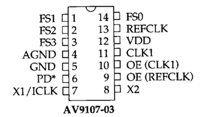
Your board uses AV9107-03CN14 clock generator.
file.php?id=31862&t=1

Screen Shot 2018-04-16 at 3.02.18 PM.png
Filename
Screen Shot 2018-04-16 at 3.02.18 PM.png
File size
32.09 KiB
Views
163 views
File license
Fair use/fair dealing exception

My deductions:
Pin 1 connects to 5V
Pin 3 connects to ground
Pin 2 of JP36, JP35 and JP34 connects to FS2, FS1 and FS0, respectively.
You can use a multimeter to confirm these.