VOGONS


First post, by aaronkatrini

User metadata
Rank Member
Rank
Member

Hi all,

This is my first time on this forum, please if I am on the wrong section move this thread. 😀
So yesterday I was on a Sunday-only place that sells second-hand stuff. And while I was looking through the electronics part (my favorite!) I came across this Diamond Monster 3D Voodoo 1.
The seller was asking only 5 euros for it. It has been a while since I wanted to try myself a 3dfx card, since I've been watching a lot of videos on YT about and could not let down that offer! However upon inspection I noticed that there were a few SMD components missing, but decided to go risk it anyway.

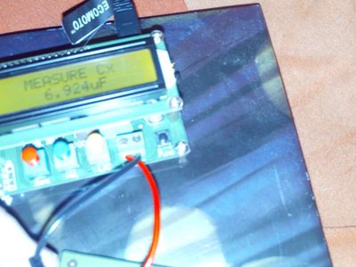
I've been searching a bit all over the internet for a schematic of the Voodoo 1 in order to know the value of these SMD "resistors"/"capacitors", but without luck. Only thing I could find was a German website that had info for the Voodoo5 5500.

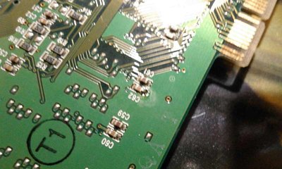
Please note that I could take a picture of the Graphics Card with my phone, but this image I'm uploading has a way better quality, and I've marked in RED all the smd components that are missing. The card I have is the exact model with the one on the photo, same revision Nr, same P/N. I haven't tried it yet on my PC because I'm afraid I can make it worse.
I'm missing :
C59
C61
C62
C63
C64
R14

ef2t5K3l.jpg

Thanks in advance.

Reply 1 of 17, by SSTV2

User metadata
Rank Oldbie
Rank
Oldbie

Hello, welcome and congratulations on a nice find!

All of the missing capacitors are simple bypass caps that can be generally ignored while testing any card/part. Note that those capacitors are grouped by two and are randomly connected in parallel, so specific cap number on PCB tells nothing about its value. My guess is that brown caps are rated for 100nF and white ones either 10nf or 1nf.

Missing resistor is probably a simple pull-up or pull-down resistor of 4.7k value (472 code translates to 47 * 10^2).

For testing, just solder in a 4.7k value resistor and that should be enough 😀

Reply 2 of 17, by Jo22

User metadata
Rank l33t++
Rank
l33t++

Hi, I've got a diamond monster 3d, too. I'll try to measure these parts, as soon as I've got a bit of free time.
I'll post back in a few days. If someone else can help, too, it would be cool! 😎

"Time, it seems, doesn't flow. For some it's fast, for some it's slow.
In what to one race is no time at all, another race can rise and fall..." - The Minstrel

//My video channel//

Reply 3 of 17, by Ozzuneoj

User metadata
Rank l33t
Rank
l33t
SSTV2 wrote:

All of the missing capacitors are simple bypass caps that can be generally ignored while testing any card/part. Note that those capacitors are grouped by two and are randomly connected in parallel, so specific cap number on PCB tells nothing about its value. My guess is that brown caps are rated for 100nF and white ones either 10nf or 1nf.

Forgive my ignorance but this seems like a good time to ask. I'm a novice at soldering and fixing circuits (getting better) and I know very little about what actually makes them work.

How do you identify a filter cap? Is it because they connect to the ground plane on one side?

Now for some blitting from the back buffer.

Reply 4 of 17, by SSTV2

User metadata
Rank Oldbie
Rank
Oldbie
Ozzuneoj wrote:

How do you identify a filter cap?

If we are talking about bypass capacitors, then good indications of it being a bypass are: it's connected as close as possible between an active components positive power pin (Vcc) and ground, also several different value capacitors might be connected in parallel to enhance frequency response characteristics of a filter.

Ozzuneoj wrote:

Is it because they connect to the ground plane on one side?

Note, a filter cap is not always connected to ground and positive power rail, most of the time it is, but in some cases, where a negative power rail is used (in relation to ground) like in OP amp circuits or PSUs, a positive capacitors terminal (anode) would be connected to ground (0V) while negative (cathode), for example, would be connected to -12V. Such configuration affects electrolytic caps mostly.

Reply 5 of 17, by aaronkatrini

User metadata
Rank Member
Rank
Member

@SSTV2 , thank you very much! Yeah i figured it out that R14 was a 4.7k resistor from the code, just asked to be sure. Its so nice of the resistors to be marked with a code so they can be identified. Too bad the capacitors aren't. Will be ordering the parts I need, I think it will take some time to arrive since I'm ordering from asia.

@Jo22 , thank you! will be looking out for your measurements, in any case I'm ordering those smd SSTV2 mentioned.

My soldering skills are not very good so i just hope I don't make any damages.

PS. Let's say IF I get the Voodoo1 to work, what should be a nice 2D card to go with it? I already have a Cirrus Logic 5440 (only 1mb) laying around. Is it appropriate or do I need to find another one?
Since I live in a big city I know a few places where they sell old electronics for cheap, what 2D card should I be looking for?

Thank you in advance. 😀

Reply 7 of 17, by appiah4

User metadata
Rank l33t++
Rank
l33t++

Matrox Mystique or Millennium II would be my option for a Windows system.

Retronautics: A digital gallery of my retro computers, hardware and projects.

Reply 8 of 17, by Jo22

User metadata
Rank l33t++
Rank
l33t++
aaronkatrini wrote:

@Jo22 , thank you! will be looking out for your measurements, in any case I'm ordering those smd SSTV2 mentioned.

Okay, you're welcome. 😀

The measurements are as following:

C59... 7,605 µF
C61... 7,470 µF
C62... 7,407 µF
C63... 7,341 µF
C64... 7,450 µF
R14... 4,63 kilo ohms

But please keep in mind that these are just estimated values.
- My LC meter can't properly measure them if they are soldered in.
Edit: R14 is labeled "472".
Edit: Note that some of the caps were in parallel, when I measured them..

"Time, it seems, doesn't flow. For some it's fast, for some it's slow.
In what to one race is no time at all, another race can rise and fall..." - The Minstrel

//My video channel//

Reply 9 of 17, by gdjacobs

User metadata
Rank l33t++
Rank
l33t++

You're measuring in circuit (therefore in parallel), so you can summarize as follows:
Capacitance values as indicated represent the max possible values for the component under test (as Ctest = Cmeas - Cext).
Resistance values as indicated represent the minimum possible values for the component under test (as Rtest=RmeasRext/[Rext-Rmeas]).

All hail the Great Capacitor Brand Finder

Reply 10 of 17, by Jo22

User metadata
Rank l33t++
Rank
l33t++
gdjacobs wrote:

You're measuring in circuit (therefore in parallel) [..]

Yup. - Also thanks for the explanation. 😀

Can we assume that the caps could *roughly* have a capacity of 4,7µF each (closest standard value),
if two of them in parallel have ~7 to 8 uF´ ?
(That's what the LC meter says. It sometimes jumps to PF values, too.)

-
I'd really love to take them out of the PCB for correct measuring (hand capacity is an issue, too),
but my hands aren't restful enough for that. 😅

If I try, I sure wouldn't be able to put them in again. 😵

Attachments

  • lc_6924.jpg
    Filename
    lc_6924.jpg
    File size
    40.2 KiB
    Views
    1804 views
    File license
    Fair use/fair dealing exception

"Time, it seems, doesn't flow. For some it's fast, for some it's slow.
In what to one race is no time at all, another race can rise and fall..." - The Minstrel

//My video channel//

Reply 11 of 17, by gdjacobs

User metadata
Rank l33t++
Rank
l33t++

You can't really make any further conclusions without a some idea of what's visible in circuit from that particular test point. You don't need to remove the component - lifting from one of the pads would be sufficient.

When they're not glued down and I don't have any chip quik, I wick up as much solder as I can on one side, then I gently lift that side of the component while applying heat alternately to both pads. By melting the solder on the other side of the component, you'll release any tension on the pad as the component rotates up.

All hail the Great Capacitor Brand Finder

Reply 12 of 17, by aaronkatrini

User metadata
Rank Member
Rank
Member

@Jo22 , thank you very much for your time!!!

The kit with the capacitors I ordered has yet to arrive. Thankfully it has these capacitors included (10 each):
- 1 UF - 2.2 UF
- 10 UF - 22 PF
- 33 PF - 330 PF
- 2.2 NF - 100 NF
- 1 NF - 220 NF
- 330 NF - 10 NF
- 10 PF - 4.7 UF
- 47 PF - 22 UF

OFF-topic:
Today I went to another Sunday-only place that sells second hand stuff, and found a couple of Graphics Cards of interest. However the price was 10 euros for each of them and hesitated a bit and didn't buy any of them but now I'm regretting it so much! These were the cards found (if I can remember correctly):
1. Nvidia GT420 purchased for 5 euros. (need this one for a home pc for my parents)
2. Cirrus Logic 54M30 (memory slot was empty - so I think only had 1mb Vram)
3. Trident (don't remember the model number but looked very dirty and in bad shape)
4. S3 Virge DX
5. 3DFX Voodoo 1 (another one!!! - and this was near mint condition, but it wasn't from Diamond but from Gainward - and wasn't as fancy looking as the diamond)
I'm still thinking of going next week and see if I can get at least one of them, but don't know... what do you guys think?
The sellers often are very keen on lowering the price, maybe I could've got both the 3dfx and the S3 for about 10-15 euros... 😢

Reply 13 of 17, by Jo22

User metadata
Rank l33t++
Rank
l33t++

You're welcome!

I hope you can get your card fixed - Good luck! 😀

gdjacobs wrote:

You can't really make any further conclusions without a some idea of what's visible in circuit from that particular test
point. You don't need to remove the component - lifting from one of the pads would be sufficient.

When they're not glued down and I don't have any chip quik, I wick up as much solder as I can on one side, then I gently lift that side of the component while applying heat alternately to both pads. By melting the solder on the other side of the component, you'll release any tension on the pad as the component rotates up.

Thanks for this tip, too! 😀 I was working with a soldering station and a desoldering pump;
I tried to gentle unsolder one side of C62 - no luck. There's still some solder on the lower corner/the underside,
which I can't reach.

I'm afraid these SMD parts are too fuzzy for my 70s era equipment (and me). 😢
- With what I have now, I'm likely broiling that SMD cap quickly.

Maybe if I had a regulated SMD soldering iron with a tiny tip..
You know, those who are used for model building (little cars, trains, etc.).

Edit: Typos fixed.

"Time, it seems, doesn't flow. For some it's fast, for some it's slow.
In what to one race is no time at all, another race can rise and fall..." - The Minstrel

//My video channel//

Reply 14 of 17, by aaronkatrini

User metadata
Rank Member
Rank
Member

Please don't ruin your precious card for me! 😀
What you have done is superb thank you very much!
If I cant fix it I'll go buy the other 3dfx I mentioned in the earlier post, if it's still there 😉

Reply 15 of 17, by Jo22

User metadata
Rank l33t++
Rank
l33t++

The card is still fine, no worries. 😀 I managed to solder the cap again.
Besides, I'm using the card for testing mainly, so it wouldn't have been that bad if I had to replace the cap.
(That's the Vooodoo card I used for my experiments with Virtual PC on Mac).

Attachments

  • c62.jpg
    Filename
    c62.jpg
    File size
    47.94 KiB
    Views
    1627 views
    File license
    Fair use/fair dealing exception

"Time, it seems, doesn't flow. For some it's fast, for some it's slow.
In what to one race is no time at all, another race can rise and fall..." - The Minstrel

//My video channel//

Reply 16 of 17, by aaronkatrini

User metadata
Rank Member
Rank
Member
Jo22 wrote:

The card is still fine, no worries. 😀 I managed to solder the cap again.

Nice! 😎

I also checked out your YT channel, interesting but I don't want to mess around with virtual pc. I remember LGR trying a voodoo card on a mac some time ago.. and it didn't go very well! 😀

The parts that I ordered haven't arrived yet though... usually it takes about 40 days to arrive here in Italy from China. But since I have some other personal stuff to deal right now, maybe it is better this way, so I will have more time to work afterwards.

Reply 17 of 17, by gdjacobs

User metadata
Rank l33t++
Rank
l33t++
Jo22 wrote:

The card is still fine, no worries. 😀 I managed to solder the cap again.
Besides, I'm using the card for testing mainly, so it wouldn't have been that bad if I had to replace the cap.
(That's the Vooodoo card I used for my experiments with Virtual PC on Mac).

Wipe up that flux, buddy!

All hail the Great Capacitor Brand Finder