VOGONS


First post, by GL1zdA

User metadata
Rank Oldbie
Rank
Oldbie

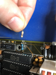
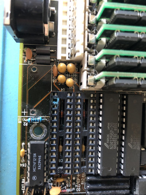
I have an Intergraph TD-30 workstation with a dual CPU 430NX based motherboard. The problem is, I get the message "Cache Memory Bad, Do Not Enable Cache!" during POST. I've managed to install DOS, but it will hang during HIMEM memory testing (it was testing for 10 minutes before I've reset the machnine). I've replaced the CPU, moved the SIMMs - makes no difference. The cache is soldered to the motherboard, I'm not skilled to replace the cache chips. Any other things I should check before I throw the PC to trash?

getquake.gif | InfoWorld/PC Magazine Indices

Reply 2 of 10, by eisapc

User metadata
Rank Member
Rank
Member

Did you try to disable the cache via BIOS or jumper?
If the cache is really bad there is no wonder you run into memory errors still using it, or are you getting the himem.sys error despite disabling the cache?
You can visually inspect the area where the cache chips are soldered and try to clean it (e.g. with an old toothbruch).
Replacing the cache chips with DIP sockets is not this complicated for someone having the right tools and experience, or does the system use QFP chips?

Reply 3 of 10, by GL1zdA

User metadata
Rank Oldbie
Rank
Oldbie

I thought the board disabled the cache. There's no BIOS setting for it. I will try the AMI Ctrl+Alt+Delete+- method next time. The board looked clean to me, I've removed dust with compressed air, but it didn't change anything. Yes, these are QFP chips, I will try to find replacements, I've found someone willing to help me with the soldering.

getquake.gif | InfoWorld/PC Magazine Indices

Reply 4 of 10, by bigwhoop

User metadata
Rank Newbie
Rank
Newbie

Since this is one of the few references online about this particular error, let me share how I fixed it on my 386 motherboard.

As it turns out, the soldered PMOS barrel battery (beneath the J1 header) sat just next to the cache memory (bank 0) so damage caused by battery leakage was my main suspicion. At a glance, the battery had only leaked a tiny amount, with very little making onto the PCB. However, some damage, as it turned out, was hidden in clear sight.

The first fault was the resistor at R2, where one of its legs had gotten completely corroded away.

The second fault was with the IC socket at U4, the fourth of the cache memory 28 pin sockets. When pulling the chip out, it was clear that green corrosion had ruined four of the pin slots. Luckily, no corrosion had made it onto the IC legs.

Desoldering and replacing the above two components got the motherboard's cache memory back to full working order! The lesson here is to very thoroughly inspect every component in the vicinity of a leaky battery, however minute the leakage may appear.

Attachments

  • IMG_4831.jpg
    Filename
    IMG_4831.jpg
    File size
    575.78 KiB
    Views
    1088 views
    File license
    Public domain
  • IMG_4850.jpg
    Filename
    IMG_4850.jpg
    File size
    930.57 KiB
    Views
    1088 views
    File license
    Public domain

Reply 5 of 10, by Sphere478

User metadata
Rank l33t++
Rank
l33t++

Good job 😀 what will you do to replace the battery?

Sphere's PCB projects.
-
Sphere’s socket 5/7 cpu collection.
-
SUCCESSFUL K6-2+ to K6-3+ Full Cache Enable Mod
-
Tyan S1564S to S1564D single to dual processor conversion (also s1563 and s1562)

Reply 8 of 10, by Sphere478

User metadata
Rank l33t++
Rank
l33t++
bigwhoop wrote on 2022-06-21, 22:16:

My apologies, I didn't see your responses until now!

Yes, I did eventually spot the battery header and built an external battery pack with 3xAAA batteries. Photos and write-up over at TinkerDifferent.

Nice. Is that the voltage it’s supposed to have? 4.5v?

Sphere's PCB projects.
-
Sphere’s socket 5/7 cpu collection.
-
SUCCESSFUL K6-2+ to K6-3+ Full Cache Enable Mod
-
Tyan S1564S to S1564D single to dual processor conversion (also s1563 and s1562)

Reply 9 of 10, by bigwhoop

User metadata
Rank Newbie
Rank
Newbie
Sphere478 wrote on 2022-06-21, 22:33:
bigwhoop wrote on 2022-06-21, 22:16:

My apologies, I didn't see your responses until now!

Yes, I did eventually spot the battery header and built an external battery pack with 3xAAA batteries. Photos and write-up over at TinkerDifferent.

Nice. Is that the voltage it’s supposed to have? 4.5v?

Thanks! I'm not sure what voltage it was designed for. I have not been able to find complete technical documentation for this motherboard.

Reply 10 of 10, by Sphere478

User metadata
Rank l33t++
Rank
l33t++
bigwhoop wrote on 2022-06-23, 02:50:
Sphere478 wrote on 2022-06-21, 22:33:
bigwhoop wrote on 2022-06-21, 22:16:

My apologies, I didn't see your responses until now!

Yes, I did eventually spot the battery header and built an external battery pack with 3xAAA batteries. Photos and write-up over at TinkerDifferent.

Nice. Is that the voltage it’s supposed to have? 4.5v?

Thanks! I'm not sure what voltage it was designed for. I have not been able to find complete technical documentation for this motherboard.

Looks like a varta is nominal at 3.6v

It seems to be a 3S pack (three cells in series)

https://en.globtek.com/nimh-battery-safety-no … d%201.3%20volts.

“NiMH Voltage
The discharge voltage profile of a NiMH battery is considered “flat” (see Figure 3.7.2 C/10 Discharge Profile @ 25°C) and varies with the rate of discharge and temperature. As a fully charged battery is discharged the voltage begins at about 1.5 volts followed by a sharp drop to around 1.3 volts. The voltage remains between 1.3 to 1.2 volts for about 75% of the profile until a second sudden drop in voltage occurs as the useful capacity of the battery begins to deplete. At this point is where the discharge current (or load) is terminated at a safe voltage level“

So full charge per cell is 1.5v

So three 1.5v AAA batteries in series actually does fall within the charge profile of a 3.6v varta.

Sphere's PCB projects.
-
Sphere’s socket 5/7 cpu collection.
-
SUCCESSFUL K6-2+ to K6-3+ Full Cache Enable Mod
-
Tyan S1564S to S1564D single to dual processor conversion (also s1563 and s1562)