VOGONS


First post, by treeman

User metadata
Rank Oldbie
Rank
Oldbie

So I have/had a Biostar MB-8433UUD-A V3 with the soldered on rtc. I attempted to remove it and install a dip socket but the chip didn't come off clean and damaged tracks, I still installed the socket hoping for a miracle but now it doesn't post it all 🙁 not even lights on keyboard when booting 🙁 I was hoping the worst case scenario would be stuck with empty battery as was before but it's much worse.

The new rtc did get warm/hot when trying to boot with no post, not sure if this is good at all, also got no post with rtc removed.

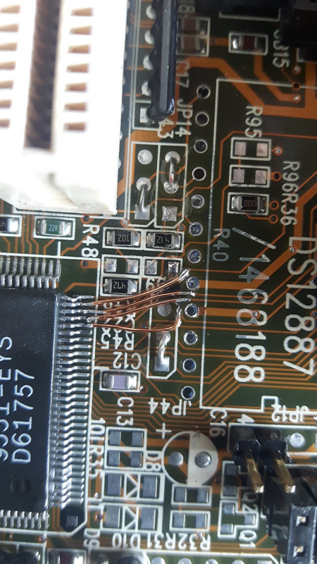
Here is a picture it looks to me that definitely that track right under the writing r40 has been ripped off, probably more damage too, not sure if its any multilayer tracks inside which got damaged too. I might take off the dip socket and try bridge that track but don't know if it's worth the effort.

Anyway I know everything I ready said not to force it desolder and pump out from the back but yeah only a few joints got sucked out successfuly others didn't want to budge and I got too excited and forced things, big lesson here.

Not sure If I am asking or simply posting my experience but any feedback welcome

Whats my chances of revival 5, 10%?
Sorry for phone pic
Screenshot_20180706_134911.png

Reply 1 of 29, by mcobit

User metadata
Rank Member
Rank
Member

If you are unsure, please give that board to someone who knows what he is doing. It might be revivable.

First test for continuety and shorts. Figure out which traces really are broken.
Then bridge them with some single strands of multicore wire.

If a pad doesn't get sucked out on first try, try again.

I have a similar board I repaird successfully after the previous owner dremelt into the board while trying to modify his rtc.

Attachments

  • 20180629_103551.jpg
    Filename
    20180629_103551.jpg
    File size
    1.08 MiB
    Views
    1571 views
    File license
    Fair use/fair dealing exception
  • 20180629_113422.jpg
    Filename
    20180629_113422.jpg
    File size
    1.1 MiB
    Views
    1571 views
    File license
    Fair use/fair dealing exception

Reply 2 of 29, by feipoa

User metadata
Rank l33t++
Rank
l33t++

I would bridge the broken traces. sounds like you will need to remove the socket, assuming you soldered one on. How else would you be testing this board otherwise? I may have a photo of this region without the socket, but I am on holiday now and am not at my computer to check. I cannot imagine a broken trace causing the RTC to heat up, that is, unless it is installed backwards.

Plan your life wisely, you'll be dead before you know it.

Reply 3 of 29, by treeman

User metadata
Rank Oldbie
Rank
Oldbie

I tried jumping everything that looked sus to me, no luck got the 3 keyboard lights flash now but no post, need a break for a while form this board. Yeah I noticed I also sliced a row on traces on the back so jumped them all
Could of all been avoided 🙁
IMG_20180706_232248.jpg
IMG_20180706_232228.jpg

Reply 4 of 29, by tpowell.ca

User metadata
Rank Member
Rank
Member

I feel sad; such a great board. 😢

  • Merlin: MS-4144, AMD5x86-160 32MB, 16GB CF, ZIP100, Orpheus, GUS, S3 VirgeGX 2MB
    Tesla: GA-6BXC, VIA C3 Ezra-T, 256MB, 120GB SATA, YMF744, GUSpnp, Quadro2
    Newton: K6XV3+/66, AMD K6-III+500, 256MB, 32GB SSD, AWE32, Voodoo3

Reply 5 of 29, by mcobit

User metadata
Rank Member
Rank
Member

The Board won't post without the rtc iirc.
So you have to reinstall it before testing.

Edit: Also I don't think it is sufficient to just stick wires into vias. You need to make a solid connection.

Reply 8 of 29, by feipoa

User metadata
Rank l33t++
Rank
l33t++

I didn't realise you ruined so many traces. I have several of these boards which I had to desolder the RTC. I do not own an automatic iron+pump and did it the old fashion way, that is, with a blue hand pump and a soldering iron. It can be quite tricky because the solder doesn't flow so easily, especially on the GND and VCC pins. You must be very very careful and need to use two different tip sizes, one small and one tiny. The tiny one is needed to jam into the via to get the under solder, but I had to crank my iron up to 850 F and do several rounds, just one one pin. At 850, you also cannot leave the iron in there long at all. This particular job, though I've done it on about 5 motherboards, was one of the more painful desolder jobs due to the state of the existing solder. You best look for version 3.1 of this board as they all should have socketed RTCs.

I also believe this board needs an RTC, irregardless of the battery state, for it to boot. You might want to find some solid core, 30 AWG wire for this repair job. It will look a lot neater.

Plan your life wisely, you'll be dead before you know it.

Reply 9 of 29, by treeman

User metadata
Rank Oldbie
Rank
Oldbie

Actually I haven't put the rtc back in, so that's next mission altho my hopes have been crushed already.

Regarding the traces on the back, since every1 is having a good laugh ill give you more material, I was using a pin to try pry out hot solder from the back of the board like some1 mentioned on one of the threads and the pin slipped accross a set of traces, didn't look too bad but when zoomed in they look cut so I bridged them all too.
Yes I was using a hand pump which was very hard, need a heater one for next time
Screenshot_20180707_112900.png

Reply 11 of 29, by treeman

User metadata
Rank Oldbie
Rank
Oldbie

Not sure, the scratch is the same color as the background, nothing shiny so didn't hurt to jump them, installed rtc and still no go, need a break from this. Going to put it aside for a while, perhaps tear it down and strart again.

I always say it's a lesson to be learnt but I should of already learnt this lesson a few tiems over, I think the key is impatience, excitement and inferior tools.

Time to get a heater Sucker instead of a hand pump for next adventure, thanks for your time and my stupidity

Reply 12 of 29, by mcobit

User metadata
Rank Member
Rank
Member

A hand solderpump is fine. As strange as it sounds: It helps to flow some fresh solder to the old leadfree stuff to get it out easier. Also some (good quality) flux will be helpful. Another method is to get some thin stainless steel tool like from the dentist. With those you can heat the solder and then gently push it through the hole and let it cool. The solder will not bond to stainless steel. So the hole will be open.
As said, you can practice (de-)soldering on some other scrap boards. Also get some thinner wire.

Reply 13 of 29, by treeman

User metadata
Rank Oldbie
Rank
Oldbie

very exciting news!

Today I decided to return to this project.
1. I ripped all the jump cables off the back, used very fine sandpaper where the suspected scratch on the traces was, after having a good look in the sun with magnifying glasses I decided they may not be cut through as suggested previously.

2. removed the dip switch, resoldered the jump cables on the front of the board under the dip switch for the original traces I broke.

3. really took my time to make sure the dip switch pins are making good contact with enough solder.

4. Noticed the umc chip near the rtc had a trace that was lifted from the motherboard but still connected so added some solder to make it stronger

5. connected the board with a pc card and nothing in the middle pc slot.

6. final attempt on the furthest pci slot from the rtc and success!

IMG_20180908_142408.jpg

IMG_20180908_142415.jpg

IMG_20180908_142836.jpg

..... however having the board sitting on post for about a minute I turned it off and noticed the cache chips were pretty hot! the cpu was warm with no heatsink but the cache chips were hot. doesn't seem right.

I am going to enjoy success for now and not turn it on until later but it seems something is not 100% right with the cache getting pretty hot.

its never been removed since it was working

Since this board died I built a isa 486 system with a oc 586 which im sure you guys have seen so I won't be using this board in one of my systems for now, but im really happy to see it alive since it has sentimental value.

I am also going to replace my isa 486 system with a 486 vlb using the same 586 cpu when the parts get it.

Reply 14 of 29, by treeman

User metadata
Rank Oldbie
Rank
Oldbie

I tried everything and the cache would became too hot to touch by the time the system booted and detected no cache.

Luckily it was the cache chips not something shorter somewhere, installing new cache + tag got this board up and running + bios settings that stick now with rtc successfully installed through a dip socket. Now time to pack it up nicely and put away for the next crazy adventure

Reply 16 of 29, by feipoa

User metadata
Rank l33t++
Rank
l33t++

Was the chipset heating up as well? What temperature was the cache? Tape your multi-meter's thermocouple to the surface or use one of those IR heat guns to measure the surface temperature. Could be that your cache has a short, or there is a short on the MB. What is the off resistance from Vcc to GND on the MB with the cache installed and uninstalled?

Plan your life wisely, you'll be dead before you know it.

Reply 17 of 29, by treeman

User metadata
Rank Oldbie
Rank
Oldbie

The only thing that was heating up excessively was the cache + tag, chipset, ram, cpu the chip with the lifted trace are cool.

before measuring voltages and temps I simply swapped cache + tag from another 486 lonestar board I got and.it detects 256 and remains cold.
During my multiple repair attempts at which I was getting desperate and probably a little careless I must of shorted something and killed the cache? not sure. But yes its a great feeling and definitely a big lesson for the future.

here is my finished switch and the 3 cables that brought it back to life.
I have installed the rtc after taking the picture and fixed the 4th pin on the dip from the left don't worry.

touched the isa slot a few times with side of solder iron so has some battle scars.

dip slot is not melted but the marks on middle barriers are from long nose pliers from installation and removal done quiet a few times.

IMG_20180908_172857.jpg

happy end, thanx every1

Reply 18 of 29, by feipoa

User metadata
Rank l33t++
Rank
l33t++

Killed the cache 'eh? Did you try the 'bad' cache in another board? Perhaps you inserted a module backwards during your panic? I've done that before, but I've adopted a habit then when working on boards, I leave my finger on the power button. If I don't hear a beep or see something on the screen within about 3 seconds, I shut it off without thinking twice.

The other thought about the cache is that I remember reading on some boards that they require cache that runs at 5 V, but is 3.3 V for I/O. I assume that 486 cache runs at 5 V and is 5 V I/O. Could the cache you are using be 5 V power and 3.3 V I/O?

Plan your life wisely, you'll be dead before you know it.

Reply 19 of 29, by Pabloz

User metadata
Rank Member
Rank
Member

that is an incredible and usefull great copper wire
where do you guys take that wire from? i have Kynar 30 awg which is used for modchips but i think the wire is very thick
that copper wire looks way thin and more usefull for motherboard repairs.

where do you guys find that wire?

20180629_113422.jpg