VOGONS


Lets make new M919 Cache sticks?

Topic actions

Reply 100 of 115, by feipoa

User metadata
Rank l33t++
Rank
l33t++

For anyone thinking of making their own M919 1024K modules and are looking for the IC's, I've done some testing you might be interested in. I tested the following SOJ and TSOP IC's in 8 ns and 10 ns speeds:
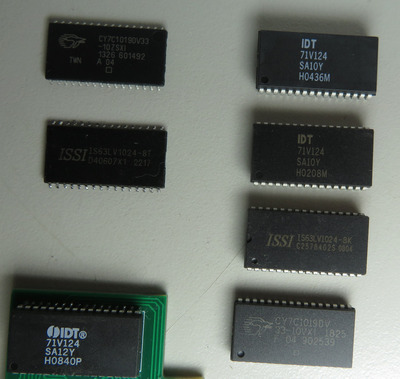
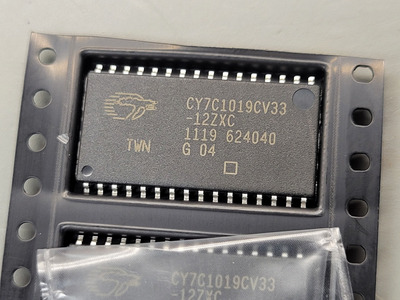
M919_1024K_SRAM_options_1.JPG
Filename
M919_1024K_SRAM_options_1.JPG
File size
652.45 KiB
Views
535 views
File license
CC-BY-4.0
M919_1024K_SRAM_options_2.JPG
Filename
M919_1024K_SRAM_options_2.JPG
File size
697.38 KiB
Views
535 views
File license
CC-BY-4.0

TSOP Cypress 10 ns
TSOP ISSI 8 ns
SOJ IDT white print 10 ns (western sourced)
SOJ IDT brown print 10 ns (China sourced)
SOJ ISSI 8 ns
SOJ Cypress 10 ns

SOJ IDT white print 12 ns (from pancakepuppy)

The results were:

failure = TSOP Cypress 10 ns
ok = TSOP ISSI 8 ns
ok = SOJ IDT white print 10 ns (western sourced)
ok = SOJ IDT brown print 10 ns (China sourced)
failure = SOJ ISSI 8 ns
failure = SOJ Cypress 10 ns

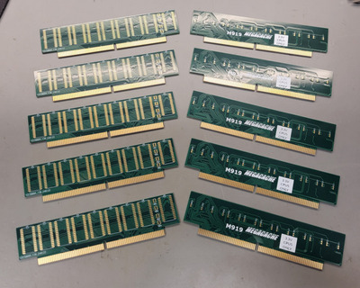
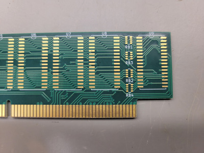
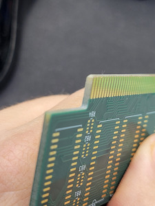
I don't understand why the font are different the between the pancakepuppy 12 ns units and the 10 ns piece I sourced. Note also that the IDT logo is missing on mine. Between the brown coloured IDT 10ns and white coloured IDT 10ns, the brown pieces have missing markers on the back.

I focused my testing primarly at 180 MHz, 2-1-2, 1/0 ws EDO DRAM read/write, and at 4.0 V. However, for the failures, I also tested at 133 MHz and 3.3 V to confirm it was't a voltage issue.

At 180 MHz testing on air (no peltier), I finally settled on the brown print IDT 10 ns chips for my cased system. I did not have the white print IDT 10ns at the time of this decision.

I did have trouble getting the TSOP ISSI 8 ns working reliably at 2-1-2, 1/0 ws, 180 MHz, 4V, 128 MB EDO. However, I retested them at 160 MHz, 2-1-2, 0/0 ws, at 3.3 V and 4.0 V, and there was no problem.

All IDT SOJ and ISSI TSOP pass at 160 MHz, 2-1-2, 0/0 ws.

Success at 180 MHz, 2-1-2, 1/0, 4V, 128 EDO depends largely on the EDO stick. I only have 1 in 4 that was happy with these tight timings.

In case anyone is looking, the ISSI 8ns TSOP chips are from aliexpress and the brown font IDT 10ns SOJ chips are from utsource. The white font IDT 10ns were sourced from Europe, but they look to be out of stock.

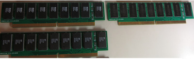
I settled on double-layer gold contacts for the M919 PCBs. Below, showing 12 ns IDT, 10 ns IDT, and 8 ns ISSI.

M919_1024K_SRAM_options_3.JPG
Filename
M919_1024K_SRAM_options_3.JPG
File size
336.95 KiB
Views
535 views
File license
CC-BY-4.0

EDIT : Reminder :
Do not use exactly 64 MB DRAM on the M919. Your benchmarks will be low due to some strange bug. Use any amount other than 64 MB.

Last edited by feipoa on 2024-02-03, 05:55. Edited 1 time in total.

Plan your life wisely, you'll be dead before you know it.

Reply 102 of 115, by feipoa

User metadata
Rank l33t++
Rank
l33t++

I only tested the USED pieces (brown font) from utsource. They don't look used to me. What I've come to realise is that utsource's "USED" could mean original used, or could mean new, remarked. I've suggested to customer service that they distinguish between the two.

I'd be interested to see what IDT71V124SA10YGI (NEW) looks like.

Plan your life wisely, you'll be dead before you know it.

Reply 103 of 115, by feipoa

User metadata
Rank l33t++
Rank
l33t++

I inquired about 10 pieces of IDT71V124SA10YGI (new), and the inquiry returned:

IDT71V124SA10YGI (used), SOJ32, 10 pieces, $40 USD. I think that's too much for 'used' pieces. From my observation, utsource's 'used' memory = 'remarked' new memory from an undisclosed manufacturer, or from the original manufacturer, but at a different speed grade.

For anything except memory chips, 'used' is typically original product desolders.

What price were you quoted? If you buy, ask for an original photo before purchase. I've seen utsource use an original product photo, but then send something with different font that looks remarked.

Plan your life wisely, you'll be dead before you know it.

Reply 104 of 115, by feipoa

User metadata
Rank l33t++
Rank
l33t++

I did some more extensive testing on the various IDT and ISSI modules for an on-the-edge stable Am5x86-180 MHz system at 2-1-2, 1/0 ws. Much fiddling around with EDO sticks is required. My conclusion is that the IDT 12ns (SOJ), IDT 10ns (SOJ), and ISSI 8ns (TSOP) are all about the same. Stability will come by playing around with the modules, just as pshipkov has determined for DIP SRAM.

That is, I have one set of 9 IDT 12ns chips that were stable on the above system, but another set of 9 which were not. I had a set of 9 ISSI 8ns chips that were stable, and another set of 9 which were not. Two sets of 9 IDT 10ns white font chips were not stable on this system, but a set of 9 IDT 10ns with brown font were stable. It is hit or miss at 180 MHz, 2-1-2, 1/0 ws.

Thus, due to cost considerations, I think sourcing the cheapest of the options makes the most sense. The cheapest are the 8 ns, ISSI, TSOP modules, at $16 USD for 10 pieces.

Keep in mind that they all worked fine at 160 MHz, 2-1-2, 0/0 ws. It was only 180 MHz that I had to start being selective.

Plan your life wisely, you'll be dead before you know it.

Reply 105 of 115, by rasz_pl

User metadata
Rank l33t
Rank
l33t

I wonder if someone made an open source SRAM speed tester. A $5 Pico rp2040 overclocked to ~300 MHz should have sufficiently fast IO for ~3.3ns resolution, could make it much more precise by changing clock speed during the test to hunt for the sweet spot.

Open Source AT&T Globalyst/NCR/FIC 486-GAC-2 proprietary Cache Module reproduction

Reply 106 of 115, by mbarszcz

User metadata
Rank Newbie
Rank
Newbie

If anyone is interested in building up a cache module for yourself. I had a few extra PCBs made. PM me if you are interested, asking $8+ shipping/PCB.

Compared to the $5 JLCPCB/PCBWay specials, apparently these boards are pretty expensive to have made with the ENIG finish, gold fingers, 4 layers (nearly $45 for 5 of them).

Attachments

Reply 107 of 115, by feipoa

User metadata
Rank l33t++
Rank
l33t++

Did you go double thickness on the gold contacts? That's what I did on my order; it was about $6 more per order. Decision was based on forum comments concerning JLCPCB's poor quality contact finish.

Plan your life wisely, you'll be dead before you know it.

Reply 108 of 115, by mbarszcz

User metadata
Rank Newbie
Rank
Newbie
feipoa wrote on 2024-02-11, 21:12:

Did you go double thickness on the gold contacts? That's what I did on my order; it was about $6 more per order. Decision was based on forum comments concerning JLCPCB's poor quality contact finish.

I got these options. How do you specify double gold thickness? My understanding is that when you specify the gold fingers, that portion of the board has thicker gold.

Layers: 4
Dimension: 133.4 mm* 33.4 mm 133.35mm* 33.43mm
PCB Thickness: 1.6
PCB Color: Green
Silkscreen: White
Material Type: FR4-Standard TG 135-140
Via Covering: Plugged
Surface Finish: ENIG
Gold Thickness: 1U"
Deburring/Edge rounding: No
Outer Copper Weight: 1 oz
Inner Copper Weight: 0.5 oz
Gold Fingers: Yes
Castellated Holes: no
Edge Plating: No
Confirm Production file: No
Silkscreen Technology: Ink-jet/Screen Printing Silkscreen
Board Outline Tolerance: ±0.2mm(Regular)

Edit: Also, I hope my Cypress chips work, they are pretty close to those 10ns ones you tested above that you said they failed. Any idea why those didn't work?

Attachments

Last edited by mbarszcz on 2024-02-11, 22:54. Edited 1 time in total.

Reply 109 of 115, by feipoa

User metadata
Rank l33t++
Rank
l33t++

I don't know why the Cypress chips didn't work. They were fake? There was one faulty piece which failed the whole chip? I don't know. It might be wise to order some IDT chips as backup in case your Cypress chips don't work.

I ordered:

Gold Thickness: 2U

Plan your life wisely, you'll be dead before you know it.

Reply 111 of 115, by mbarszcz

User metadata
Rank Newbie
Rank
Newbie

I built two of these modules. I've done a decent amount of SMD soldering, but man are these an exercise in patience to build up. The pads are barely big enough for the TSOP packages to the point where you are basically soldering under the legs with nothing sticking out. Maybe if you used a stencil with paste the hot air would work well, but I wouldn't recommend hand applied paste and hot air at all. I wound up having to touch up most of the joints by hand. My solder paste is a little old so I'm sure that didn't help either.

The first one I built out of new SRAM chips from digikey (https://www.digikey.com/en/products/detail/in … 3-10VXI/1543796). I eventually got this one working perfectly. There were a few solder pads not making contact with the SOJ legs, but once I got that sorted out everything seems to be golden.

The second one I built out of CY7C1019CV33-12ZXC ebay chips. This one I just cannot get to work no matter what I've tried. I ordered enough chips to build two of these, but after the first one didn't work I went over my soldering multiple times with a fine toothed comb, I ohmed out all the connections between the chips and the connector, and eventually resorted to swapping out the chips systematically 2 at a time on the board. In the end though, I still could not get it to work.

For anyone that stumbles across this thread and is having trouble, I've noticed there seem to be a few conditions that I ran into with these cache modules and the M919 motherboard, none of which in my case had anything to do with the type of RAM (fpm/edo), capacity, BIOS version, CMOS settings or jumpers. Maybe this will help someone:

Condition 1:
- The system powers on but nothing appears on the screen when the module is inserted
- Likely cause: short circuits somewhere in the soldering (best case data/address lines bridged together somewhere, worst case power/ground)

Option 2:
- The system powers on, detects the 1024K during post, but never uses it (cacheckh/speedsys acts like there is no L2 cache)
- Likely causes:
1. One or more of the chips has a pin that is not making good contact with the solder pad on the board (one of the address/data lines)
2. One or more of the chips is faulty
- If you see the cache size show up but its not working, this doesn't seem to be due to any misconfiguration, there is likely a fault with the cache module but it doesn't say anything.

Option 3:
- The system powers on, detects the 1024K during post, and uses it properly (cacheckh/speedsys uses the L2 cache and you can see the throughput somewhere between the L1 and Memory speeds.
- Likely cause: you got lucky

During my troubleshooting it seems that there must be some sort of cache check/self test that occurs during post that is not very descriptive or well documented. This is just speculation, but the first part of the check seems like it tries to address the cache and if it can, it shows the size (1024K). The second (silent) part seems like it tries to write data into the cache and then read it back, and if there are any issues at all, it silently doesn't use the L2 cache despite already showing that the cache was detected.

feipoa, what failure modes did you have with the failed chips? Did the system fail to post at all? Show the size but not work? Instability? Something else?

I'm thinking with all the flakey chips out there, maybe it's just best just to buy legit chips from digikey instead of taking a gamble and wasting hours soldering hundreds of little pads only to wind up with ewaste.

Reply 112 of 115, by rasz_pl

User metadata
Rank l33t
Rank
l33t
mbarszcz wrote on 2024-02-18, 20:00:

The pads are barely big enough for the TSOP packages to the point where you are basically soldering under the legs with nothing sticking out.

Do you mean you dont like soldering SOJ, or the footprint is too narrow? erm, I used even narrower SOJ footprints on https://github.com/raszpl/FIC-486-GAC-2-Cache-Module, hope it comes out ok 😀
SOJ is pretty nice to solder using Hoof/Spoon drag soldering tip.

mbarszcz wrote on 2024-02-18, 20:00:

wouldn't recommend hand applied paste and hot air at all.

Chinese $10 SOJ hotair nozzle are pretty cool if you go hotair

mbarszcz wrote on 2024-02-18, 20:00:

The second one I built out of CY7C1019CV33-12ZXC ebay chips. This one I just cannot get to work no matter what I've tried. I ordered enough chips to build two of these, but after the first one didn't work I went over my soldering multiple times with a fine toothed comb, I ohmed out all the connections between the chips and the connector, and eventually resorted to swapping out the chips systematically 2 at a time on the board. In the end though, I still could not get it to work.

I think SRAM tester is in order 😀 rp2040 has 30 GPIO, just enough for 128KB cache chip.

mbarszcz wrote on 2024-02-18, 20:00:

During my troubleshooting it seems that there must be some sort of cache check/self test that occurs during post that is not very descriptive or well documented. This is just speculation, but the first part of the check seems like it tries to address the cache and if it can, it shows the size (1024K). The second (silent) part seems like it tries to write data into the cache and then read it back, and if there are any issues at all, it silently doesn't use the L2 cache despite already showing that the cache was detected.

I looked up what Award ASUS Bios is doing. https://github.com/raszpl/430FXL2Cache Afaik there are two phases. First is Cache size detection, but later when initializing cache there is ram test that might detect errors and try without cache.

Open Source AT&T Globalyst/NCR/FIC 486-GAC-2 proprietary Cache Module reproduction

Reply 113 of 115, by feipoa

User metadata
Rank l33t++
Rank
l33t++

I agree that the TSOPs are more of a burden to solder on because the pads aren't long enough. Using solder paste doesn't work well because of this. I found that using some tackier no-clean flux paste and hand soldering each pin worked best. All the ISSI 8 ns chips I used have been fine.

I did not try CY7C1019CV33. Mine were 1018. I suspect the 1018's are incompatible for some reason. We now have 3 attempts and 3 failures.

I cannot find my notes, so from memory, my symptoms were:
Cypress SOJ or Cypress TSOP: with one of the modules the screen stayed blank at power on. For the other set, system booted, but no L2 detected. ISSI SOJ chips were always detected at POST and cachechk sometimes showed the 1024K and sometimes it did not. I spent probably 2 hours going over each chip thinking it must be a solder joint, but in the end, I could not find a bad joint.

For the cost, I think the ISSI 8ns TSOP chips are the best bet. For the digikey modules, after shipping and tax, it would cost $40 USD to obtain 9 chips of those CY7C1018DV33-10VXI modules.

Plan your life wisely, you'll be dead before you know it.

Reply 114 of 115, by mbarszcz

User metadata
Rank Newbie
Rank
Newbie
rasz_pl wrote on 2024-02-18, 21:13:

Do you mean you dont like soldering SOJ, or the footprint is too narrow? erm, I used even narrower SOJ footprints on https://github.com/raszpl/FIC-486-GAC-2-Cache-Module, hope it comes out ok 😀

I feel like the the footprint is too wide for SOJ and too narrow for TSOP.

The SOJ were definitely easier to solder than the TSOP, but I agree they were much better suited to being soldered to drag soldering/manual soldering with an iron. Since I did these first, my mistake was coming out of the gate trying to solder the SOJs with hot air and paste (hoping they'd align themselves and stick like soldering SMD resistors/caps), but with the overly long pad extending outward and the relatively high curving leg of the chip, the solder paste just spread out on the PCB and didn't "suck up" the leg like I had hoped, so I had to go back and add more solder by hand anyway.

rasz_pl wrote on 2024-02-18, 21:13:

I looked up what Award ASUS Bios is doing. https://github.com/raszpl/430FXL2Cache Afaik there are two phases. First is Cache size detection, but later when initializing cache there is ram test that might detect errors and try without cache.

Sounds like I was pretty close. It would be nice if it was a bit more verbose though or if there was a program to more thoroughly diagnose what works and what doesn't after boot time. Also I agree that raspi sram tester would be handy, but I wouldn't have the first clue how to design one of those.

feipoa wrote on 2024-02-18, 21:28:

I agree that the TSOPs are more of a burden to solder on because the pads aren't long enough. Using solder paste doesn't work well because of this. I found that using some tackier no-clean flux paste and hand soldering each pin worked best. All the ISSI 8 ns chips I used have been fine.

100% agree

feipoa wrote on 2024-02-18, 21:28:

For the cost, I think the ISSI 8ns TSOP chips are the best bet.

Do you have a link to the aliexpress ISSI TSOPs or the name of the seller? These maybe? https://www.aliexpress.us/item/32568045478887 … 7Cquery_from%3A

feipoa wrote on 2024-02-18, 21:28:

For the digikey modules, after shipping and tax, it would cost $40 USD to obtain 9 chips of those CY7C1018DV33-10VXI modules.

I try not to think about that 😆. At least I have a working cache module now.

Reply 115 of 115, by feipoa

User metadata
Rank l33t++
Rank
l33t++

Those look the correct parts, but I ordered from a different seller with name: Shop910355040,
https://www.aliexpress.com/item/1005001375396 … .21ef1802erbguU

$16 USD shipped for 10 pieces.

Have you tried your Digikey sourced Cypress chips at 180 MHz, 2-1-1-1, 1/0 ws EDO?

Plan your life wisely, you'll be dead before you know it.