VOGONS


First post, by ildonaldo

User metadata
Rank Member
Rank
Member

Hello,
I am building a 486 machine at the moment and I'd like to add a speed display to the case.
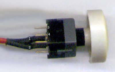
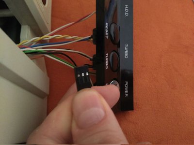
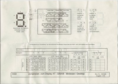
The case has currently only a Turbo Button and a Turbo-LED but I have been able to lay hands on a AT-325 A/B speed display that will fit in the front dashboard.

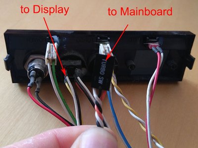
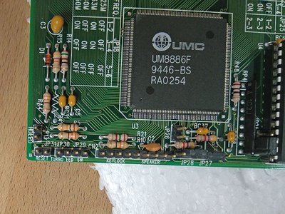
... and now I want to properly wire this to the Display and the board (QDI MP4-P4U885P3 PCB V2.0).

Can you please help me with the correct wiring for that?

blende_s.jpg
Filename
blende_s.jpg
File size
79.42 KiB
Views
376 views
File comment
Front Dashboard of Case with (short) 3-wire Turbo-connector
File license
Fair use/fair dealing exception
display.jpg
Filename
display.jpg
File size
311.71 KiB
Views
376 views
File comment
Manual of Display
File license
Fair use/fair dealing exception
board_s.jpg
Filename
board_s.jpg
File size
112.91 KiB
Views
376 views
File comment
Board Turbo-connectors
File license
Fair use/fair dealing exception

(board manual see: http://www.elhvb.com/mobokive/archive/Qdi%20- … ls/p4u885g2.pdf)

Thank you in advance
ildonaldo

Building my own PCs since 1991 - for my retro builds it's "no CF-disks, no Floppy emulators, no modern cases etc.", only the real and authentic stuff whenever possible.

Reply 1 of 4, by PARKE

User metadata
Rank Oldbie
Rank
Oldbie

The turbo button needs 2x2 sets of wires. This example below needs two extra wires on pins 3 & 4.

turbo2.jpg
Filename
turbo2.jpg
File size
45.51 KiB
Views
359 views
File license
Fair use/fair dealing exception

2 wires go to the motherboard and 2 wires go to the display and connect to either 3 & 4 LOW or 5 & 4 HIGH.
5volt power for the display has to come from a power supply (molex) plug.
The turbo led on the frontpanel is fed by the motherboard.

The original buttons had 2x3 wires (for versatility between different board layouts) but only 2x2 are actually needed.
http://www.suntekpc.com/htm-2/power-switch-pu … urbo-3p3c-2.htm

Reply 2 of 4, by ildonaldo

User metadata
Rank Member
Rank
Member

I now ripped the pc apart and found the second wire to the mainboard, but it is a 3-wire connector.
Any hint, which wires to connect to the mainboard (either black+red or black+white)?
(otherwise it is a try an error case)

connecotors.jpg
Filename
connecotors.jpg
File size
56.64 KiB
Views
353 views
File comment
Turboswitch connectors
File license
Fair use/fair dealing exception

Building my own PCs since 1991 - for my retro builds it's "no CF-disks, no Floppy emulators, no modern cases etc.", only the real and authentic stuff whenever possible.

Reply 3 of 4, by PARKE

User metadata
Rank Oldbie
Rank
Oldbie

Ok, you have the right button, I could not see that in the first photo. The black one in the middle is always connected. Whether you need white or orange depends on the motherboard. Two possibilities: the motherboard is default in turbo mode or default in non-turbo mode. You need to connect the button so that it works as intended when pressed in -or- pressed out. If you do not have enough space on your motherboard to switch the 3-wire Dupont plug 180 degrees in synchronicity with the plug on the display you have to remove the wire that you do not need (either white or orange) and cut the plug to size (neater is then to replace the 3-wire plug with a 2-wire and a 1-wire plug)

Reply 4 of 4, by ildonaldo

User metadata
Rank Member
Rank
Member

OK, I will check with a continuity tester.

Building my own PCs since 1991 - for my retro builds it's "no CF-disks, no Floppy emulators, no modern cases etc.", only the real and authentic stuff whenever possible.