VOGONS


First post, by kokerich

User metadata
Rank Newbie
Rank
Newbie

Found this board in my basement few days ago. Seemed interesting 8 simm sockets, 25Mhz cpu, I have a nice working ITT 287 for it etc.
The board says MG PRODUCT MG-2862002 REV. 1.2
After brief inspection I figured out that some parts are missing, BIOS ROM, jumpers, maybe something else I don't know.
Chipset is Headland ht21 and I found one rom file that may be the one (2hlm004.zip), the board has only one ROM chip 27512.
I couldn't find any info on jumper setting so anyone with any ideas is welcome to jump in.

Attachments

  • 20180927_014036.jpg
    Filename
    20180927_014036.jpg
    File size
    1.77 MiB
    Views
    1614 views
    File license
    Fair use/fair dealing exception

Reply 1 of 22, by jxalex

User metadata
Rank Member
Rank
Member

BIOS rom? But what is that with the word "AMI" ? It is a BIOS, but is it for keyboard ONLY?
Or actually the OPTION ROM is what you thought?

THe BIOS Battery (or the battery holder ) recommended to solder where it is marked that "lithium 3.6V".
When having following expansion cards: one multi IO controller; display card; and one memory simm, then it can be checked already though?

if you need the EPROM burning then with that I could help, also I have fresh blank chips.

Current project: DOS ISA soundcard with 24bit/96Khz digital I/O, SB16 compatible switchable.
newly made SB-clone ...with 24bit and AES/EBU... join in development!

Reply 4 of 22, by Jo22

User metadata
Rank l33t++
Rank
l33t++
jxalex wrote:

BIOS rom? But what is that with the word "AMI" ? It is a BIOS, but is it for keyboard ONLY?

My guess is that this is the keyboard microcontroller (8042 derivative). Not sure why it has an AMI label onto it.
I've seen that quite often in the past, still makes no sense to me.
Maybe AMI also made custom firmware for the KBC ? 😕

Predator99 wrote:

Whats wrong with the ZIP you found? If there is a HI/LO image in it you need to combine it to one file.

Easier said than done, I think. Where should he know from how to "combine" such odd/even files.
I found utilites for that purpose, but they are cryptic and for *nix platform only.

"Time, it seems, doesn't flow. For some it's fast, for some it's slow.
In what to one race is no time at all, another race can rise and fall..." - The Minstrel

//My video channel//

Reply 5 of 22, by Predator99

User metadata
Rank l33t
Rank
l33t

Take a look inside the Hi and lo bins and you will see. There are strings in with every second Letter missing. After combining it needs to be complete.

There is a Windows hex Editor you can Use. Will take a look at the Name at home.

Reply 6 of 22, by jesolo

User metadata
Rank l33t
Rank
l33t

Have a look here: http://arvutimuuseum.ee/th99/#1
You might be able to identify your motherboard under the "286" section.
Since your motherboard has simm slots near the keyboard connector, it should be easy to spot.

Reply 8 of 22, by kokerich

User metadata
Rank Newbie
Rank
Newbie

Thanks for quick help there.
First of all AMI chip is keyboard bios only, the board needs EPROM for SYSTEM BIOS which is a totaly different thing. But I think it would not be a problem, I have a bunch of good EPROM chips and a good EPROM programmer and even the file that I found is one file instead of two (64k instead of 2 x 32k). The only question is whether the file is apropriate for this MB. In other words do all the boards with ht21 chipset have the same ROM?
We'll see after burning the ROM if the board wakes up. I also have the NOS lithium 3.6V battery to solder, no problem there 😉
Hopefuly in the end we'll se how to fit FPU with it's oscilator.
Right now the only problem are jumper settings, I looked at th99 and I couldn't find anything, I'll look again.
Maybe we could guess some of them:
JP10 could be external/internal battery connector/switch
JP3 - oscillator for the FPU (if the clock is the same than it uses internal, CPU's frequency)
JP4 is maybe mono/color or something
JP5,6,7,8,9 probably speaker, turbo, keylock, reset etc.
JP11 have no idea.
TP1 maybe CMOS clear.

Last edited by kokerich on 2018-09-27, 09:06. Edited 1 time in total.

Reply 9 of 22, by quicknick

User metadata
Rank Oldbie
Rank
Oldbie
Predator99 wrote:

Take a look inside the Hi and lo bins and you will see. There are strings in with every second Letter missing. After combining it needs to be complete.

There is a Windows hex Editor you can Use. Will take a look at the Name at home.

WinHex. (Tools>File Tools>Unify)

Reply 10 of 22, by jesolo

User metadata
Rank l33t
Rank
l33t

There are other utilities available that allows you to combine (merge) ODD and EVEN BIOS ROM images into one BIOS ROM image.
Will have to dig a bit to see what I have.

Reply 11 of 22, by kokerich

User metadata
Rank Newbie
Rank
Newbie

OK, here is the update, after I programmed EPROM with 2hlm004.bin 64kB file the board woke up, memory test passed, got to the point of OS loader. The only thing suspicios is the speaker which beeps short beeps repedeately. Still there are mystery jumper settings that I'm worried about, and about inserting FPU unit, I am not sure whether it uses onboard oscillator or I need to plug in one more.
Also I woud like to test the motherboard so it would be nice if you can recommend me some good tools for that.

Attachments

  • 20180928_153823.jpg
    Filename
    20180928_153823.jpg
    File size
    187.81 KiB
    Views
    1462 views
    File license
    Fair use/fair dealing exception
  • 20180928_153802.jpg
    Filename
    20180928_153802.jpg
    File size
    1.96 MiB
    Views
    1462 views
    File license
    Fair use/fair dealing exception

Reply 12 of 22, by SW-SSG

User metadata
Rank Oldbie
Rank
Oldbie
kokerich wrote:

... and about inserting FPU unit, I am not sure whether it uses onboard oscillator or I need to plug in one more.

25MHz 287s don't exist, so unless you're OK with overclocking the one that you have, you will need to plug in a suitable oscillator for your 287.

Nice to see that it is alive...

Reply 13 of 22, by root42

User metadata
Rank l33t
Rank
l33t

Beautiful board!

Wasn't it so that the 287 was usually clocked independently?

YouTube and Bonus
80486DX@33 MHz, 16 MiB RAM, Tseng ET4000 1 MiB, SnarkBarker & GUSar Lite, PC MIDI Card+X2+SC55+MT32, OSSC

Reply 14 of 22, by kokerich

User metadata
Rank Newbie
Rank
Newbie

25MHz 287s don't exist, so unless you're OK with overclocking the one that you have, you will need to plug in a suitable oscillator for your 287.

I am well aware of that fact, my IIT is rated 20MHz so maybe it can pull it out on 25.
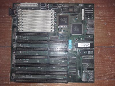
Still I have a dillema. There are three crystals on board: one standard 14.318MHz, one on 50MHz (obviously for the main CPU) and one on 32MHz maybe for a FPU.

I've seen boards with three crystals without a socket for a custom crystal for the FPU. Usually the third crystal is for the FPU.
Also there is a mystery jumper which I guess is for clock selection for the 287 (onboard crystal or added).
Still I guess the best solution is to get 40MHz crystal and insert it into the socket. I guess there is a way to somehow check the clock of the 287 in software.

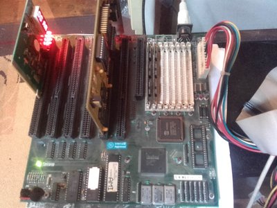
In the meanwhile I tried to test the board but I ran into problems.
The problem of short beeps disapeared when I put the jumper on JP4 right beside the keyboard BIOS. Still I don't know the meaning of this.
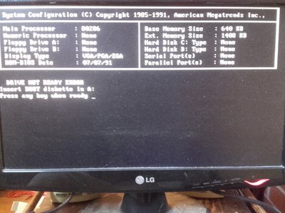
Real problem is the keyboard. After starting up, the keyboard works just fine. I can enter the CMOS settings and diags move aroung for ever, everything works.
But when it reaches the point of loading OS the keyboard stops working while the system is running further, machine does not freeze, it boots the DOS with no problem.
Diagnostic card shows no problem.

Reply 15 of 22, by root42

User metadata
Rank l33t
Rank
l33t

Can't you measure on pin 32 of the FPU socket what clock is fed to the FPU? Needs an appropriate multimeter or logic analyzer... 😀

YouTube and Bonus
80486DX@33 MHz, 16 MiB RAM, Tseng ET4000 1 MiB, SnarkBarker & GUSar Lite, PC MIDI Card+X2+SC55+MT32, OSSC

Reply 16 of 22, by bjwil1991

User metadata
Rank l33t
Rank
l33t

What happens when you remove the jumper? Does the keyboard still act up? Have you checked the solder joints on the keyboard controller for any missing, cold, or cracks? I would also check the capacitors as well and replace them.

Discord: https://discord.gg/U5dJw7x
Systems from the Compaq Portable 1 to Ryzen 9 5950X
Twitch: https://twitch.tv/retropcuser

Reply 17 of 22, by kokerich

User metadata
Rank Newbie
Rank
Newbie

When I remove the JP4 everything works the same but there are endless short beeps comming out of the speaker (very anoying). Nothing to do with the keyboard fail.
It's interesting that while in setup/diags of the BIOS, keyboard can work for hours but when OS stars to boot it stops immediately (strange).

Can't you measure on pin 32 of the FPU socket what clock is fed to the FPU? Needs an appropriate multimeter or logic analyzer... 😀

I doubt that my multimeter can measure MHz 😁 😁 😁

Reply 18 of 22, by stamasd

User metadata
Rank l33t
Rank
l33t
kokerich wrote:
When I remove the JP4 everything works the same but there are endless short beeps comming out of the speaker (very anoying). Not […]
Show full quote

When I remove the JP4 everything works the same but there are endless short beeps comming out of the speaker (very anoying). Nothing to do with the keyboard fail.
It's interesting that while in setup/diags of the BIOS, keyboard can work for hours but when OS stars to boot it stops immediately (strange).

Can't you measure on pin 32 of the FPU socket what clock is fed to the FPU? Needs an appropriate multimeter or logic analyzer... 😀

I doubt that my multimeter can measure MHz 😁 😁 😁

There are cheap frequency counters available, here's one identical to the one I use: https://www.amazon.com/0-1MHz-Signal-Frequenc … equency+counter
They're very useful to have around.

I/O, I/O,
It's off to disk I go,
With a bit and a byte
And a read and a write,
I/O, I/O

Reply 19 of 22, by kokerich

User metadata
Rank Newbie
Rank
Newbie

Well, I must admit that I can't delay buying a freqmeter and/or logic analizer anymore 😉

In the meanwhile I traced the PCB which confirmed what I thought earlier. Third crystal (32MHz) is traced to the JP3 which selects between that crystal and the one in the Y4 thus selecting the frequency for 287.
No worries about FPU, the keyboard is the main problem now. 🙁