VOGONS


First post, by oldgames79

User metadata
Rank Newbie
Rank
Newbie

Hi,

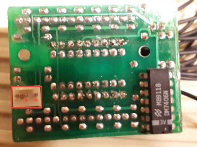
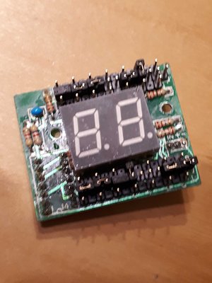
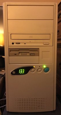
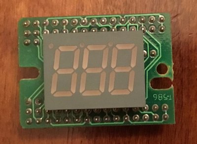
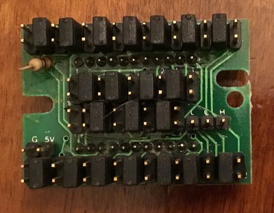
I have a Turbo 2 digit with only 3 pin with "-" "+" "In" (see on the pictures).

I can connect the 5V but I have no connector for the turbo switch ????

Someone knows this kind of turbo switch ? and how I can connect the turbo switch ????

Thanks

20190125_080149.jpg
Filename
20190125_080149.jpg
File size
524.52 KiB
Views
784 views
File license
Fair use/fair dealing exception

Reply 1 of 19, by treeman

User metadata
Rank Oldbie
Rank
Oldbie

so its a 3 pin switch, I think some motherboards have a 3 pin header with 5v G and turbo signal (IN)

But I can't see how the display connects to turbo button, can you take a picture from the front?

The original cable must be spliced in some way that the IN and G connects to the turbo button and runs to the motherboard TB SW header

so When pressing the button it sends signal to the led display to switch and also sends signal to motherboard to close circuit on TB SW

Reply 3 of 19, by gdjacobs

User metadata
Rank l33t++
Rank
l33t++

Each 2x3 cell of headers (with two pins missing) corresponds to one of the elements of the 7 segment display. The jumper switch is used to connect above, to the right, or below the center pin. Those positions correspond to the segment being lit with turbo on, turbo off, or both.

You're going to have to test and determine which orientation is for each state, which bank corresponds to which digit, and the segment order (usually the outer segments, clockwise, starting at the top followed by the middle).

All hail the Great Capacitor Brand Finder

Reply 4 of 19, by treeman

User metadata
Rank Oldbie
Rank
Oldbie

if I was to take a guess I would say shorting "-" and "IN" should change the led state and if so that would also be spliced into a second cable that goes to the motherboard TB SW header

Then im guessing "+" which is 5v would be spliced from the molex 5v pin and "-" would be ground, the TB SW would be sharing the same ground "-" with the 5v power connection

I never seen this type of led in action so its my operation theory

Reply 5 of 19, by Intel486dx33

User metadata
Rank l33t
Rank
l33t

I could not get my Turbo switch to work also as I do not have the instructions for the setting up the LED indicator.
So I was able to figure out the basic LED functions and set the numerals up.

As for the "Turbo" switch I used this method.
https://youtu.be/YjGWj8d_gMk?t=353

Toggle switch
https://www.ebay.com/itm/5X-Toggle-SWITCH-ON- … 8f508:rk:4:pf:0

Cables
https://www.ebay.com/itm/5Pcs-PC-computer-mot … 9kFJ:rk:31:pf:0

Attachments

  • IMG_0296.jpeg
    Filename
    IMG_0296.jpeg
    File size
    1.1 MiB
    Views
    678 views
    File license
    Fair use/fair dealing exception
  • IMG_0289.JPG
    Filename
    IMG_0289.JPG
    File size
    237.41 KiB
    Views
    678 views
    File license
    Fair use/fair dealing exception
  • IMG_0294.JPG
    Filename
    IMG_0294.JPG
    File size
    313.99 KiB
    Views
    678 views
    File license
    Fair use/fair dealing exception

Reply 6 of 19, by oldgames79

User metadata
Rank Newbie
Rank
Newbie
treeman wrote:

if I was to take a guess I would say shorting "-" and "IN" should change the led state and if so that would also be spliced into a second cable that goes to the motherboard TB SW header

Then im guessing "+" which is 5v would be spliced from the molex 5v pin and "-" would be ground, the TB SW would be sharing the same ground "-" with the 5v power connection

I never seen this type of led in action so its my operation theory

I have try this method but it doesn't work.
Probably, This two digit display work only with a specific motherboard.

If someone have a 2 or 3 digit to sell, I'm interested.

Reply 8 of 19, by treeman

User metadata
Rank Oldbie
Rank
Oldbie

If you read the original post he has no issue with the power or the led display setup

I don't think many. 386 486 era motherboards have fan connectors on the motherboard, the way the led displays are wired from the factory is usually a cable direct to the psu with 5v or spliced off the molex

"I can connect the 5V but I have no connector for the turbo switch ????"

Reply 9 of 19, by oldgames79

User metadata
Rank Newbie
Rank
Newbie

Yes, the 2 digit work but as there is no connector for switching 66 to 33Mhz.

There are 3 pin on the 2digit board and I have five wire to connect (2 for the 5v and 3 for the turbo button).

Reply 10 of 19, by Intel486dx33

User metadata
Rank l33t
Rank
l33t

Yeah, That's what I have on the back of my LED.
But I could not get Turbo to work.
And I could not get the LED to switch numbers from 133 to 33.

I have 2 pins that read "Ground and 5v"
And I have 3 pins that read "L,C,H" but I don't know what that means ? These go to the turbo switch but my turbo pin on the motherboard are only 2-pins.

Attachments

  • IMG_0294.JPG
    Filename
    IMG_0294.JPG
    File size
    313.99 KiB
    Views
    636 views
    File license
    Fair use/fair dealing exception

Reply 11 of 19, by treeman

User metadata
Rank Oldbie
Rank
Oldbie

When L+C is jumpered = Low
C+H = High
This 3 pins go direct to the turbo button which has 3 pins in 2 rows

1 row goes from LCH the other row goes to the motherboard, if you have 2 pins connect the first 2 from the 3

Reply 12 of 19, by oldgames79

User metadata
Rank Newbie
Rank
Newbie
Intel486dx33 wrote:
Yeah, That's what I have on the back of my LED. But I could not get Turbo to work. And I could not get the LED to switch numbers […]
Show full quote

Yeah, That's what I have on the back of my LED.
But I could not get Turbo to work.
And I could not get the LED to switch numbers from 133 to 33.

I have 2 pins that read "Ground and 5v"
And I have 3 pins that read "L,C,H" but I don't know what that means ? These go to the turbo switch but my turbo pin on the motherboard are only 2-pins.

It s the difference with my display board. I have 3 pin for 5v / ground / in. I don t have LCH and I can connect the turbo switch

Reply 13 of 19, by Intel486dx33

User metadata
Rank l33t
Rank
l33t
treeman wrote:
When L+C is jumpered = Low C+H = High This 3 pins go direct to the turbo button which has 3 pins in 2 rows […]
Show full quote

When L+C is jumpered = Low
C+H = High
This 3 pins go direct to the turbo button which has 3 pins in 2 rows

1 row goes from LCH the other row goes to the motherboard, if you have 2 pins connect the first 2 from the 3

Yes, I only have 2-pins on the motherboard turbo connector. So it's either open or closed to enable turbo.
So you are saying "L and C" is all I need to enable turbo mode ?

Reply 14 of 19, by Intel486dx33

User metadata
Rank l33t
Rank
l33t
oldgames79 wrote:
Intel486dx33 wrote:
Yeah, That's what I have on the back of my LED. But I could not get Turbo to work. And I could not get the LED to switch numbers […]
Show full quote

Yeah, That's what I have on the back of my LED.
But I could not get Turbo to work.
And I could not get the LED to switch numbers from 133 to 33.

I have 2 pins that read "Ground and 5v"
And I have 3 pins that read "L,C,H" but I don't know what that means ? These go to the turbo switch but my turbo pin on the motherboard are only 2-pins.

It s the difference with my display board. I have 3 pin for 5v / ground / in. I don t have LCH and I can connect the turbo switch

You can set your LED to read "Hi" or "L0" or "33" or "66". I would just use a power switch cable to enable turbo mode.

Reply 15 of 19, by treeman

User metadata
Rank Oldbie
Rank
Oldbie

the turbo button has 2 rows of 3 pins each row is independent of each other.

The function is when you. press the button on each row either pin 1 +2 or 2+3 is selected

for the led. display you have 3 pins so either c+l or c+h is selected using the button

if you plug the middle button pin and the top or bottom pin to your motherboard TB SW one of the combinations will close the circuit on the TB SW header enabling/disabling the turbo when your press the button

so 1 cable from turbo goes to led display (3pins)
second cable goes from turbo button to TB SW on motherboard (2pins) one of them has to be middle pin from turbo switch

Reply 16 of 19, by PARKE

User metadata
Rank Oldbie
Rank
Oldbie

The reasoning behind the 3-pin connection is that the button should be able to service different types of motherboards - they can rely on open as well as closed jumpers to enable turbo. The original 2x3 way button looks like this but only 2x2 pins/cables are actually used in any configuration:
http://www.suntekpc.com/htm-2/power-switch-pu … urbo-3p3c-2.htm

Reply 17 of 19, by treeman

User metadata
Rank Oldbie
Rank
Oldbie

this is why I had my theory for bridging the "IN" and "-" for the original post just the 2 pins.

Maybye this type of led is designed for a special button/motherboard combo.

3 pins connect to the button then 3 pins go to the motherboard, there is motherboards that have a 5v header on 3 pins.

I will quote this post which I started while ago
Fried my turbo button

tpowell.ca wrote: […]
Show full quote

tpowell.ca wrote:

What I discovered is that the motherboard, in my case a MS-4144 has 3 turbo pins, 1 ground, 1 for turbo-disabling and 1 at 5v in that order. (GND disblTURBO 5volt)
The switch however has a different order of pins, where the common pin comes first, then NO and lastly NC. (COMMON NO NC)
NC = normally closed, NO = normally open

The only other way to switch states on the ORIGINAL post led would be to send some current to the IN pin which notifies led to change from LOW to HIGH or other way around but I don't know how high

Reply 18 of 19, by PARKE

User metadata
Rank Oldbie
Rank
Oldbie
treeman wrote:

this is why I had my theory for bridging the "IN" and "-" for the original post just the 2 pins.
Maybye this type of led is designed for a special button/motherboard combo.

The chip on the backside also suggests that this is not the common simple type.

Reply 19 of 19, by treeman

User metadata
Rank Oldbie
Rank
Oldbie

its a funny position to have 5v in the middle, perhaps this type of 3 pin switch works like this:
default mode "-" and "+" connected = power to led LOW state
"-" and "+" and "IN" bridged = power to led HIGH STATE

there can only be 3 logical inputs to "IN"

1. close circuit with "-"
2. supply 5v to change state (risk of burnout)
3. supply unknown low voltage current to change state

but having 5v going through the power button will melt the button, so the motherboard would have to send the 5v direct to the led and cut it when button pressed.