VOGONS


First post, by Intel486dx33

User metadata
Rank l33t
Rank
l33t

I have a motherboard that is loaded with Windows98se.
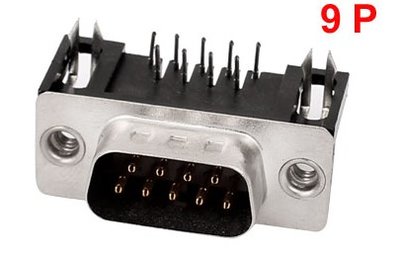
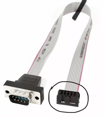
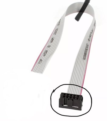
All the serial ports show up as working in “device manager”
But the mouse is not detected in Win98se.

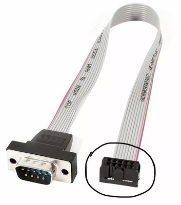
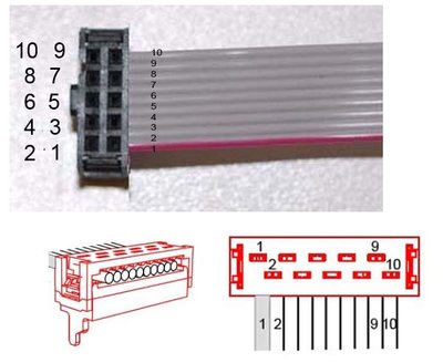
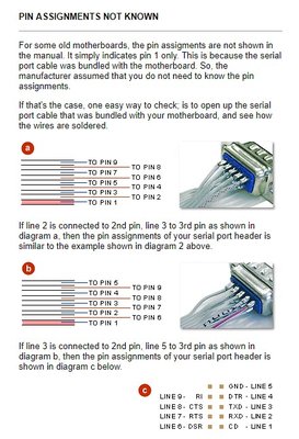
So I am assuming I am using the wrong serial cables.
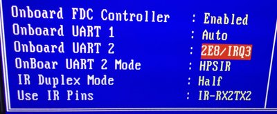
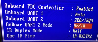
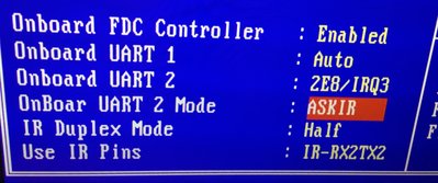
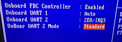
I don’t think it is a bios issue because Win98se lists the serial ports as working.

I added an ISA serial port adapter and confirmed that the operating system is working correctly and that the serial mouse works.
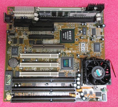
The Motherboard is:
Motherboard - Soyo-SY-5EHM, baby ATX, 3-ISA, 3-PCI, AGP
Cache - 512kb.
RAM - 2x256mb. = 512mb. total
CPU - AMD K6-3-450 over clocked to 500mhz.
Chipset - VIA
BIOS - Award.

Attachments

Reply 1 of 17, by Deksor

User metadata
Rank l33t
Rank
l33t

Check out the manual of the board to see if you cannot find the pinout if those serial port. There used to be two serial port header standards back then

Trying to identify old hardware ? Visit The retro web - Project's thread The Retro Web project - a stason.org/TH99 alternative

Reply 2 of 17, by Intel486dx33

User metadata
Rank l33t
Rank
l33t

I checked the manual and it does not specify what type of serial port it is.
Only COM1 and COM2 and Soyo serial ribbon.

What com port setting do I need in the BIOS to get this to work ?

Reply 3 of 17, by Deksor

User metadata
Rank l33t
Rank
l33t

You cannot change it, it's hardwired. You need to find the correct serial port to connect on these headers

Trying to identify old hardware ? Visit The retro web - Project's thread The Retro Web project - a stason.org/TH99 alternative

Reply 4 of 17, by GigAHerZ

User metadata
Rank Oldbie
Rank
Oldbie

Well, the cable is either staggered or sequential on the port side. Just resolder it the other way around and you're done.

Yes, there are 2 parallel standards in existance...

"640K ought to be enough for anybody." - And i intend to get every last bit out of it even after loading every damn driver!

Reply 5 of 17, by appiah4

User metadata
Rank l33t++
Rank
l33t++

See here: Serial port breakout bracket not working after motherboard change

Retronautics: A digital gallery of my retro computers, hardware and projects.

Reply 6 of 17, by Intel486dx33

User metadata
Rank l33t
Rank
l33t

Here are the BIOS settings I have available for the serial ports. I tried several RS232 DB9 serial port ribbons but None seem to work.

Attachments

Reply 7 of 17, by Deksor

User metadata
Rank l33t
Rank
l33t

I repeat, the problem isn't in the configuration, it's just how they wired it up. It's like showing me the BIOS setup where you set up drives for a CD drive using the mitsumi or panasonic interface. Even though they both look like IDE, they'll never work on an IDE port.

Trying to identify old hardware ? Visit The retro web - Project's thread The Retro Web project - a stason.org/TH99 alternative

Reply 8 of 17, by Intel486dx33

User metadata
Rank l33t
Rank
l33t
GigAHerZ wrote:

Well, the cable is either staggered or sequential on the port side. Just resolder it the other way around and you're done.

Yes, there are 2 parallel standards in existance...

So if I set my bios com port settings to “Auto” it should be okay right.
So if I clip the cable on the connector with that make it “staggered” ?

Attachments

Last edited by Intel486dx33 on 2019-04-21, 18:29. Edited 1 time in total.

Reply 9 of 17, by appiah4

User metadata
Rank l33t++
Rank
l33t++
Intel486dx33 wrote:
GigAHerZ wrote:

Well, the cable is either staggered or sequential on the port side. Just resolder it the other way around and you're done.

Yes, there are 2 parallel standards in existance...

So if I set my bios com port settings to “Auto” it should be okay right.
So if I flip the cable on the connector with that make it “staggered” ?

No to both questions.

Retronautics: A digital gallery of my retro computers, hardware and projects.

Reply 10 of 17, by Intel486dx33

User metadata
Rank l33t
Rank
l33t

Look at this image.
Which diagram is staggered ?

Attachments

Reply 11 of 17, by meljor

User metadata
Rank Oldbie
Rank
Oldbie

You can not just grab a connector, it needs to be the same pinout as the board. Finding the right one can be hard. Check your manual and use a multimeter.

asus tx97-e, 233mmx, voodoo1, s3 virge ,sb16
asus p5a, k6-3+ @ 550mhz, voodoo2 12mb sli, gf2 gts, awe32
asus p3b-f, p3-700, voodoo3 3500TV agp, awe64
asus tusl2-c, p3-S 1,4ghz, voodoo5 5500, live!
asus a7n8x DL, barton cpu, 6800ultra, Voodoo3 pci, audigy1

Reply 12 of 17, by Intel486dx33

User metadata
Rank l33t
Rank
l33t

I think this is what I am looking for.
http://www.frontx.com/pro/cpx102_2.html

And this

Attachments

  • DB9-002.jpg
    Filename
    DB9-002.jpg
    File size
    95.68 KiB
    Views
    698 views
    File license
    Fair use/fair dealing exception
  • DB9-001.jpg
    Filename
    DB9-001.jpg
    File size
    21.27 KiB
    Views
    698 views
    File license
    Fair use/fair dealing exception

Reply 13 of 17, by appiah4

User metadata
Rank l33t++
Rank
l33t++

Hey it's not rocket science, now that I have more time let me explain.

This is the pinout of a DB9:

1 2 3 4 5
6 7 8 9

This is what a Linear header looks like:

1 2 3 4 5
6 7 8 9 0

This is what a Staggered header looks like:

1 3 5 7 9
2 4 6 8 0

Now get a multimeter, go to continuity mode, hold one terminal to the Pin 2 of your non-working cable's DB9, then use the other terminal to determine which location it is connected to. This will tell you whether it's Linear or Staggered. If it's Linear, get a Staggered header. If it's Staggered, get a Linear header.

If you work out that you need a Staggered cable replacement, you are in luck because that is the later standard and is often found on mid-late Pentium boards so 90% chance anything NOS you order online will work. If you find you need a Linear cable replacement, you will have to scavenge your parts bin or ask around because I don't think you can reliably find and order one.

Retronautics: A digital gallery of my retro computers, hardware and projects.

Reply 14 of 17, by Intel486dx33

User metadata
Rank l33t
Rank
l33t

Okay, I have some Rasberry pi wires that I can hook up to the serial ribbon to find out the pin-outs using a voltage meter. Then can cut the serial ribbon in half and solder up the wires correctly as to the diagram.
Easy fix.

Attachments

Last edited by Intel486dx33 on 2019-03-01, 06:06. Edited 1 time in total.

Reply 15 of 17, by appiah4

User metadata
Rank l33t++
Rank
l33t++
Intel486dx33 wrote:

Okay, I have some Rasberry pi wires that I can hook up to the serial ribbion to find out the pin-outs.
I am also going to use these rasberry pi wires to create a new ribbion mod.

Let us know how that works; the dupont jumper wires should do the trick, but if you have a solder type DB9 you will have to cut off the male ends, strip them and solder them onto the DB6. There are things like this you can get away with without soldering, though I'm not sure how good an idea that is:

serial-ribbon-connector-3-500x500.jpg

Retronautics: A digital gallery of my retro computers, hardware and projects.

Reply 16 of 17, by GigAHerZ

User metadata
Rank Oldbie
Rank
Oldbie

Take the plastic part off from the port side (the side that mounts to a case) and just rewire it the other way around. There are 2 options, how it is wired currently and you just need the other option...

"640K ought to be enough for anybody." - And i intend to get every last bit out of it even after loading every damn driver!

Reply 17 of 17, by Intel486dx33

User metadata
Rank l33t
Rank
l33t

I think I will try these connectors they seem simple enough.
I can just cut off the old DB9 connector and add this NEW one to the ribbon.

Attachments