VOGONS


First post, by tayyare

User metadata
Rank Oldbie
Rank
Oldbie

I recently grabbed that Cooler Master Cavalier 2 CAV-T02 case/chassis.

WhatsApp%20Image%202019-03-04%20at%2018_59_33.jpg
Filename
WhatsApp%20Image%202019-03-04%20at%2018_59_33.jpg
File size
159.31 KiB
Views
861 views
File license
Fair use/fair dealing exception

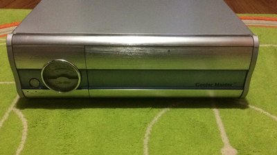
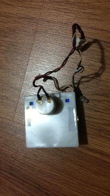
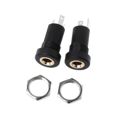
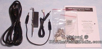
It has a analog VU meter but available information about it is very slim to say the least. It supposed to come with a bracket that should somehow connect it to a souncard's or motherboard's speaker jack, but it is missing.

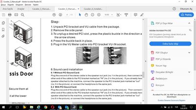
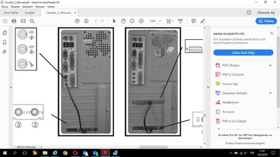
I found a low res picture of the accesory, and a manual for similar but different case

050106215799650.jpg
Filename
050106215799650.jpg
File size
36.63 KiB
Views
861 views
File license
Fair use/fair dealing exception
Clip1.jpg
Filename
Clip1.jpg
File size
160.16 KiB
Views
861 views
File license
Fair use/fair dealing exception
Clip.jpg
Filename
Clip.jpg
File size
113.57 KiB
Views
861 views
File license
Fair use/fair dealing exception

http://www.google.com.tr/url?sa=t&rct=j&q=&es … 9LSOR_HfzL1lF7t

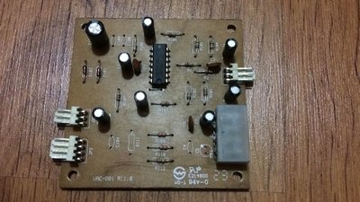
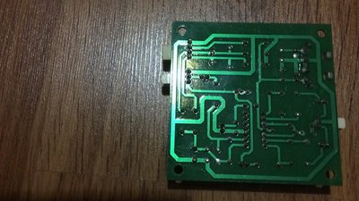
And here is the picture showing VU meter PCB and where the input should go (3 pin male connector at he left, just under the power molex):

WhatsApp Image 2019-03-04 at 21.39.50.jpeg
Filename
WhatsApp Image 2019-03-04 at 21.39.50.jpeg
File size
118.98 KiB
Views
861 views
File license
Fair use/fair dealing exception

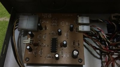
What do you think? If I just somehow connect the speaker out from the board (Left channel, right channel, ground) driectly to this, will it work?

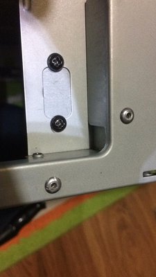
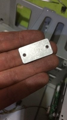
Or this mising black box/backplate combo is not a simple breakout box, but has a PCB hidden inside that supposed to make some kind of a conversion?

Thanks in advance 😊

Last edited by tayyare on 2019-03-05, 11:28. Edited 1 time in total.

GA-6VTXE PIII 1.4+512MB
Geforce4 Ti 4200 64MB
Diamond Monster 3D 12MB SLI
SB AWE64 PNP+32MB
120GB IDE Samsung/80GB IDE Seagate/146GB SCSI Compaq/73GB SCSI IBM
Adaptec AHA29160
3com 3C905B-TX
Gotek+CF Reader
MSDOS 6.22+Win 3.11/95 OSR2.1/98SE/ME/2000

Reply 1 of 7, by mdog69

User metadata
Rank Newbie
Rank
Newbie

Whatever is on the back panel, it has to be passive - the only connections appear to be the two 3.5mm connections exposed on the back plate, and (looking at the cable) a 2.5mm plug inside the case which then connects to the spare connector below the molex power connector.

Can you:
1) Extract the VU meter PCB from the case, and take a clear photo of both sides of the PCB
2) Confirm the markings shown on the integrated circuit U1. (no picture required for that bit - just read it and tell us what it says.
3) Trace where JP1 and JP2 cables go to

The VU meter board doesn't look complicated, and it might be possible to deduce a circuit diagram, and from that confirm/guess what the contents of the rear panel connector were.

(My only concern is that the "common" connection from a PC speaker outlet may not be at ground level - especially if the speaker amplifier is "bridged". In this situation connecting the common to the PC 0v line might stop audio output working)

Reply 2 of 7, by tayyare

User metadata
Rank Oldbie
Rank
Oldbie
mdog69 wrote:
Whatever is on the back panel, it has to be passive - the only connections appear to be the two 3.5mm connections exposed on the […]
Show full quote

Whatever is on the back panel, it has to be passive - the only connections appear to be the two 3.5mm connections exposed on the back plate, and (looking at the cable) a 2.5mm plug inside the case which then connects to the spare connector below the molex power connector.

Can you:
1) Extract the VU meter PCB from the case, and take a clear photo of both sides of the PCB
2) Confirm the markings shown on the integrated circuit U1. (no picture required for that bit - just read it and tell us what it says.
3) Trace where JP1 and JP2 cables go to

The VU meter board doesn't look complicated, and it might be possible to deduce a circuit diagram, and from that confirm/guess what the contents of the rear panel connector were.

(My only concern is that the "common" connection from a PC speaker outlet may not be at ground level - especially if the speaker amplifier is "bridged". In this situation connecting the common to the PC 0v line might stop audio output working)

1- Of course I can do
2- Same as above
3- JP1 goes to a front panel "volume dial" thing, JP2 goes to the VU meter itself and two LEDs that illuminates it.

Thnaks a lot for the expert answer, 😀 I'll return back with the requested info tonight.

GA-6VTXE PIII 1.4+512MB
Geforce4 Ti 4200 64MB
Diamond Monster 3D 12MB SLI
SB AWE64 PNP+32MB
120GB IDE Samsung/80GB IDE Seagate/146GB SCSI Compaq/73GB SCSI IBM
Adaptec AHA29160
3com 3C905B-TX
Gotek+CF Reader
MSDOS 6.22+Win 3.11/95 OSR2.1/98SE/ME/2000

Reply 3 of 7, by PC Hoarder Patrol

User metadata
Rank l33t
Rank
l33t

Hope some of these help

installation guide - https://web.archive.org/web/20061207124031/ht … anual/final.pdf

datasheet - https://web.archive.org/web/20070415102631/ht … /cavalier24.pdf

VU-Meter Howto - https://web.archive.org/web/20050819154021/ht … CAVT02_1206.pdf

FAQ - https://web.archive.org/web/20070407205718if_ … duct_ID=CAV-T02

Reply 4 of 7, by tayyare

User metadata
Rank Oldbie
Rank
Oldbie
mdog69 wrote:
Whatever is on the back panel, it has to be passive - the only connections appear to be the two 3.5mm connections exposed on the […]
Show full quote

Whatever is on the back panel, it has to be passive - the only connections appear to be the two 3.5mm connections exposed on the back plate, and (looking at the cable) a 2.5mm plug inside the case which then connects to the spare connector below the molex power connector.

Can you:
1) Extract the VU meter PCB from the case, and take a clear photo of both sides of the PCB
2) Confirm the markings shown on the integrated circuit U1. (no picture required for that bit - just read it and tell us what it says.
3) Trace where JP1 and JP2 cables go to

The VU meter board doesn't look complicated, and it might be possible to deduce a circuit diagram, and from that confirm/guess what the contents of the rear panel connector were.

(My only concern is that the "common" connection from a PC speaker outlet may not be at ground level - especially if the speaker amplifier is "bridged". In this situation connecting the common to the PC 0v line might stop audio output working)

Here are the photos:

WhatsApp Image 2019-03-05 at 22.01.11.jpeg
Filename
WhatsApp Image 2019-03-05 at 22.01.11.jpeg
File size
251.62 KiB
Views
792 views
File license
Fair use/fair dealing exception
WhatsApp Image 2019-03-05 at 22.00.18.jpeg
Filename
WhatsApp Image 2019-03-05 at 22.00.18.jpeg
File size
219.2 KiB
Views
792 views
File license
Fair use/fair dealing exception
WhatsApp Image 2019-03-05 at 22.02.28.jpeg
Filename
WhatsApp Image 2019-03-05 at 22.02.28.jpeg
File size
221.21 KiB
Views
792 views
File license
Fair use/fair dealing exception

GA-6VTXE PIII 1.4+512MB
Geforce4 Ti 4200 64MB
Diamond Monster 3D 12MB SLI
SB AWE64 PNP+32MB
120GB IDE Samsung/80GB IDE Seagate/146GB SCSI Compaq/73GB SCSI IBM
Adaptec AHA29160
3com 3C905B-TX
Gotek+CF Reader
MSDOS 6.22+Win 3.11/95 OSR2.1/98SE/ME/2000

Reply 5 of 7, by tayyare

User metadata
Rank Oldbie
Rank
Oldbie
PC Hoarder Patrol wrote:
Hope some of these help […]
Show full quote

Hope some of these help

installation guide - https://web.archive.org/web/20061207124031/ht … anual/final.pdf

datasheet - https://web.archive.org/web/20070415102631/ht … /cavalier24.pdf

VU-Meter Howto - https://web.archive.org/web/20050819154021/ht … CAVT02_1206.pdf

FAQ - https://web.archive.org/web/20070407205718if_ … duct_ID=CAV-T02

Thnaks a lot for the documentation! 😀

GA-6VTXE PIII 1.4+512MB
Geforce4 Ti 4200 64MB
Diamond Monster 3D 12MB SLI
SB AWE64 PNP+32MB
120GB IDE Samsung/80GB IDE Seagate/146GB SCSI Compaq/73GB SCSI IBM
Adaptec AHA29160
3com 3C905B-TX
Gotek+CF Reader
MSDOS 6.22+Win 3.11/95 OSR2.1/98SE/ME/2000

Reply 6 of 7, by mdog69

User metadata
Rank Newbie
Rank
Newbie

OK the quick version:
Get a length of twin screened cable - cable that has two cores surrounded by an overall screen.

At the VU meter board end, wire it to a 0.1 molex connector.

Pin 1: Core #1
Pin 2: Screen
Pin 3: Core #2

The other end gets soldered to the speaker outputs on the back of your sound card.
Screen goes to 0v, the two other cores go to left and right.
Note that it doesn't matter which cable goes to left or to right - the two signals get added together on the VU meter board anyway.

From the documentation provided earlier in the post, the "volume control" is actually a sensitivity control for the VU meter.
If the needle hits maximum all the time, turn the sensitivity down.
If the needle doesn't move enough, turn the control up.
Once you've got it set right, you shouldn't need to change it.

The long bit:
I couldn't read the IC part number, so I put a bet on it being an LM324 quad op-amp.

For the record, the circuit does the following:
The signal comes in on pins 1 and 3, and each channel is AC coupled to the input of a separate inverting amplifier.
The outputs of the two amplifiers are then summed together, passed through the front panel "sensitivity" control and then into a third op-amp which drives the meter.
The whole thing runs off the +5v supply, which also feeds the VU meter LEDs via a resistor.

I think I can reasonably say:
The back panel module is just three sockets paralleled up, two facing outside, one facing inside.
The sensitivity control is probably a simple potentiometer, with the track connected to pins 1&3 and the wiper to pin 2.
The VU meter module probably contains just a meter, and an unknown number of LEDs with no dropper resistor (that's done by R112 on the PCB)

I've got a scruffy hand drawn circuit diagram that I'll scan and attach later for those who are interested.

/md69

Reply 7 of 7, by tayyare

User metadata
Rank Oldbie
Rank
Oldbie

Thnaks a lot for all the detailed information, and of course for your effort, I really appreciated it.

Soldering something on the sound card is a no for me, first of all I really suck at soldering and also I really don't want to fiddle with my only SB32 that way.

Instead, I will do something like this: I ordered the below parts:

HTB1XTybRXXXXXXOXpXXq6xXFXXXf.jpg
Filename
HTB1XTybRXXXXXXOXpXXq6xXFXXXf.jpg
File size
78.67 KiB
Views
778 views
File license
Fair use/fair dealing exception
HTB1i3i0BQKWBuNjy1zjq6AOypXab.jpg
Filename
HTB1i3i0BQKWBuNjy1zjq6AOypXab.jpg
File size
101.61 KiB
Views
778 views
File license
Fair use/fair dealing exception

I will solder a fan extension cable to the 3.5mm socket above (because of the 0.1 molex connector at its end), which will be assembled on to a small sheet of metal with a hole drilled on it:

WhatsApp Image 2019-03-04 at 21.24.02.jpeg
Filename
WhatsApp Image 2019-03-04 at 21.24.02.jpeg
File size
141.15 KiB
Views
778 views
File license
Fair use/fair dealing exception
WhatsApp Image 2019-03-04 at 21.22.08.jpeg
Filename
WhatsApp Image 2019-03-04 at 21.22.08.jpeg
File size
123.99 KiB
Views
778 views
File license
Fair use/fair dealing exception

Then I use the splitter above externally: OneI jack will go into the sound card speaker out, the other jack will go into the the newly created "input port", and socket end will be mating with my speaker jack.

Very much the same way actually that the document above describes. Is there any problems that you can see with it? (apart from the use of an unshielded cable)

Againi, thanks a lot for all the help! 🤣

GA-6VTXE PIII 1.4+512MB
Geforce4 Ti 4200 64MB
Diamond Monster 3D 12MB SLI
SB AWE64 PNP+32MB
120GB IDE Samsung/80GB IDE Seagate/146GB SCSI Compaq/73GB SCSI IBM
Adaptec AHA29160
3com 3C905B-TX
Gotek+CF Reader
MSDOS 6.22+Win 3.11/95 OSR2.1/98SE/ME/2000