VOGONS


Reply 20 of 51, by dekkit

User metadata
Rank Member
Rank
Member
TheNoOne wrote:

Please measure the voltage you get on GPIO 14/17, should be above 2.5V. Maybe the pullup resistor on the motherboard is not low enough? Also, is the Pico LED blinking when you pressing keys?

Interesting... I am getting 1.43V on both GPIO 14 (red probe on GPIO 14 and black on Ground) and also 1.43.when measuring GPIO17 to ground.

Pico is getting just a little over 4.53V from the ps/2 socket.

I'm getting very faint led blinks on key press.

The low voltage on the gpio helps explain the key keyboard error on this 486 SBC. I'll try a different system with a ps/2 port.

Also it is quite possible my single board computer (SBC) project doesnt hasnt implemented all pull up circuitry for its ps/2 ports (it has no documentation) - and this discovery may help resolve an issue with its mouse port not registering despite being enabled in eeprom.

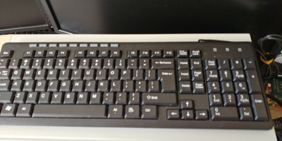
UPDATE - it works on my pentium 4 using a range of cheap dell usb keyboards YEY!

One bug ive noticed is control of num lock and caps lock leds on the keyboard itself. Functionally the modes work well (ie. num lock will engage and type numbers vs become arrow keys) but all 3 x key leds will flick on then off. Where as expected behaviour is only the num lock led will engage and stay on until mode is changed.

Overall very impressed with how this all works. Great project.

Reply 21 of 51, by TheNoOne

User metadata
Rank Newbie
Rank
Newbie
dekkit wrote on 2023-01-22, 00:42:

Interesting... I am getting 1.43V on both GPIO 14 (red probe on GPIO 14 and black on Ground) and also 1.43.when measuring GPIO17 to ground.

Ahh! That might be the problem. You can always add two additional 22k or 10k pullup resistors between PS/2 clock and data and 5V respectively.
The zener diode might pull down the voltage too much, thats why I switched to the bidirectional level shifter on the second project.
You could also try out a voltage divider, but this might damage the pico: https://github.com/No0ne/ps2pico/tree/eee620a … 38b65f850#usage

dekkit wrote on 2023-01-22, 00:42:

Pico is getting just a little over 4.53V from the ps/2 socket.

That should be fine.

dekkit wrote on 2023-01-22, 00:42:

I'm getting very faint led blinks on key press.

Ah yes, since I switched over to the Pico PIOs the CPU doesn't have to sleep anymore while transmitting and so the board led gets very dim (might fix this in the future).

dekkit wrote on 2023-01-22, 00:42:

Functionally the modes work well (ie. num lock will engage and type numbers vs become arrow keys) but all 3 x key leds will flick on then off.

Thats odd, could you make a short video of that behavior?

Reply 22 of 51, by dekkit

User metadata
Rank Member
Rank
Member
TheNoOne wrote on 2023-01-22, 06:33:
Ahh! That might be the problem. You can always add two additional 22k or 10k pullup resistors between PS/2 clock and data and 5V […]
Show full quote
dekkit wrote on 2023-01-22, 00:42:

Interesting... I am getting 1.43V on both GPIO 14 (red probe on GPIO 14 and black on Ground) and also 1.43.when measuring GPIO17 to ground.

Ahh! That might be the problem. You can always add two additional 22k or 10k pullup resistors between PS/2 clock and data and 5V respectively.
The zener diode might pull down the voltage too much, thats why I switched to the bidirectional level shifter on the second project.
You could also try out a voltage divider, but this might damage the pico: https://github.com/No0ne/ps2pico/tree/eee620a … 38b65f850#usage

dekkit wrote on 2023-01-22, 00:42:

Pico is getting just a little over 4.53V from the ps/2 socket.

That should be fine.

dekkit wrote on 2023-01-22, 00:42:

I'm getting very faint led blinks on key press.

Ah yes, since I switched over to the Pico PIOs the CPU doesn't have to sleep anymore while transmitting and so the board led gets very dim (might fix this in the future).

dekkit wrote on 2023-01-22, 00:42:

Functionally the modes work well (ie. num lock will engage and type numbers vs become arrow keys) but all 3 x key leds will flick on then off.

Thats odd, could you make a short video of that behavior?

I'll set up the pentium rig again and take some pic / video - this is using a cheap usb keyboard thats only a year so old.

The sequence is this (once all connected)
- Power on PC
- keyboard leds all light up as per normal power on
- once system boots to a linux live disc menu (cd)
- I press 'num lock'
- all 3 keyboard leds flick on briefly then back off

Will update this post with more video shortly (if it will allow)

20230122_181224_HDR.jpg
Filename
20230122_181224_HDR.jpg
File size
1.19 MiB
Views
1560 views
File license
CC-BY-4.0
20230122_181155.jpg
Filename
20230122_181155.jpg
File size
1.9 MiB
Views
1560 views
File license
CC-BY-4.0

Ill private message you to see if I can send you the video directly.

Reply 23 of 51, by dekkit

User metadata
Rank Member
Rank
Member

I suspect it might be a timing/ sync issue as I understand when using these types of keys the pc takes control of the communication. and sends information back to the keyboard as to which leds to illuminate etc.

Btw tried on 2 x different keyboards...similar behaviour.

Reply 24 of 51, by TheNoOne

User metadata
Rank Newbie
Rank
Newbie

Ok first I thought it was a USB issue but now I think its a PS/2 issue. On which motherboard does this happen? Do you have a serial ttl to usb cable (or another pi pico)? I can compile you an UF2 file which sends out all PS/2 bytes for debugging. Also please try the non-PIO version which has different timings: https://github.com/No0ne/ps2pico/releases/dow … 0.6/ps2pico.uf2

(thanks for the video, I'm not allowed to send PMs yet)

Reply 25 of 51, by dekkit

User metadata
Rank Member
Rank
Member

I dont have a serial TTL cable but I should be able find spare arduino nano in the kitty somewhere which should do the same thing - ill need to find space / time to setup properly before i request a debug version.

In the interim, I'll give that other build a go later in week.

Its a pentium 4 - mainboard was from towards the end of the era. I'll open it up and let you know.. Found a pic...its an asrock p4i65g
https://www.asrock.com/mb/intel/p4i65g/

If there are various timings to tweak - i can test a few different timing files and report back until i can setup better debugging.

Reply 26 of 51, by dekkit

User metadata
Rank Member
Rank
Member
TheNoOne wrote on 2023-01-22, 14:29:

Ok first I thought it was a USB issue but now I think its a PS/2 issue. On which motherboard does this happen? Do you have a serial ttl to usb cable (or another pi pico)? I can compile you an UF2 file which sends out all PS/2 bytes for debugging. Also please try the non-PIO version which has different timings: https://github.com/No0ne/ps2pico/releases/dow … 0.6/ps2pico.uf2

(thanks for the video, I'm not allowed to send PMs yet)

Test results just in:
486 system aka 'the fussy one'
- 10k pull up resistors = no change, keyboard tested did not register
- replaced code with "ps2pico/releases/download/v0.6/ps2pico.uf2" = no change, each keyboard tested resulted in keyboard error press F1 (note - I powered down between each keyboard swap over)
- in all cases LEDs on pico itself seem to work ok.
Worth mentioning that i have ps/2 keyboard that works fine with this 486 setup but i imagine it is more unforgiving with timing/ event driven communication. I am happy to try the combined mouse and keyboard one but would need to order parts.

Pentium 4 aka 'the one that worked'
- replaced code with "ps2pico/releases/download/v0.6/ps2pico.uf2" = didn't error on boot but no keyboard presses worked (ie using arrows keys in menus didn't register at all)
- LEDs on pico itself seem to work ok at first, but would then stop responding.
- previous latest version worked fine except for keyboard leds flickering when i used caps lock / num lock etc.

FYI - I have a spare Arduino Nano - could possibly used to get debugging / monitoring info if that helps.

Reply 29 of 51, by dekkit

User metadata
Rank Member
Rank
Member

ok no dice with this 486, same issues as before (keyboard not detected errors on boot). I just tried using version 1.0. This was on the PCB i had the pull ups on.

What is the difference with the XT variant? should I be using that one instead (i believe its electrically / signal compatible yeah?)

Update #1 - tried with the XT variant 1.0 on the 486, and still no luck. The LED on the pico seems more responsive on buttons, but the 486 still results in a keyboard error on boot.

Reply 30 of 51, by TheNoOne

User metadata
Rank Newbie
Rank
Newbie

The XT version is only for 8088/8086/286 CPUs on an XT motherboard like the IBM 5160 or NuXTv2. Motherboards with 386 or higher all use AT or PS2 protocol, electrically its the same but the protocol is different.

Please try the attached firmware with serial debugging and hook up a serial to usb device on Pin1 TX/GPIO0 and Pin3 GND.
You can also use another Pi Pico for that, see: https://github.com/raspberrypi/picoprobe

After connecting with a serial terminal program on 115200bps you should see something like this after turning on the PC:

noone@imac20 ~ % screen /dev/cu.usbmodem14302 115200
ps2pico-1.1 DEBUG=true
HID device address = 1, instance = 0 is mounted
HID Interface Protocol = Keyboard
HID device address = 1, instance = 1 is mounted
ps2_send: aa
IRQ ps2_receive: fe
ps2_send: aa
IRQ ps2_receive: ff
ps2_send: fa
ps2_send: aa
ps2_send: 05
ps2_send: f0
ps2_send: 05
ps2_send: e0
ps2_send: 72
ps2_send: e0
ps2_send: f0
ps2_send: 72
ps2_send: e0
ps2_send: 72
ps2_send: e0
ps2_send: f0
ps2_send: 72

I captured that on my 486.

Attachments

  • Filename
    ps2pico-debug.zip
    File size
    30.07 KiB
    Downloads
    38 downloads
    File license
    Fair use/fair dealing exception

Reply 31 of 51, by dekkit

User metadata
Rank Member
Rank
Member

Ok, give me a few days to solder some header pins onto a spare nano and I'll take some measurements to help get to the bottom of this.

Does it do any handshakes with the pc on boot? Are there any timing settings I can play with to help dial it in?

Reply 32 of 51, by TheNoOne

User metadata
Rank Newbie
Rank
Newbie

Thanks for helping debugging this!

Yes, after power-on/reset the BIOS sends an 0xff which means reset for the keyboard. After that the keyboard is expected to send 0xfa for ACK and then blinks the three LEDs and sends a 0xaa for self-test completed.
The OS does run some more commands but in the case of my log output: I went strait to the BIOS setup screen.

The timing is controlled by the PIO on the pico which runs at 133Mhz/2560 with a clock pulse using 4 cycles the clock runs at ~13kHz which should be in spec (10~16 kHz).
If we want to debug timing I'll have to send you another more verbose version of the debug firmware. Or you can use a logic analyzer if you have one at hand.

Reply 33 of 51, by Azarien

User metadata
Rank Oldbie
Rank
Oldbie

That's a very interesting project, now I need to order a Pico or two 😉

About those lock LEDs not supported yet - do you think it'll require any extra wiring and components, or it's just a firmware thing?

Reply 34 of 51, by TheNoOne

User metadata
Rank Newbie
Rank
Newbie

Num lock, caps lock and scroll lock are now supported as they should be. This was just an early firmware build on page 1. The only "problem" in the XT version is the state of these LEDs is generated in the picos ram because a normal XT keyboard does not have such LEDs.

Reply 35 of 51, by dekkit

User metadata
Rank Member
Rank
Member

Ok soldered in some pins to nano and pico so I can wire it up and then will run thru some tests this weekend.

Test setup:
- pico version with the pull ups (to rule out voltage pull up issues) + firmware linked above.
- arduino nano with RX (nano) wired to TX (pico GPIO pin 1) and ground ls shared
- I'll use the arduino ide serial monitor to get some readings on boot.

Reply 36 of 51, by dekkit

User metadata
Rank Member
Rank
Member

Excuse the format, i'm still messing with an arduino sketch to get it reading the RX pin properly.

18:52:07.013 -> p
18:52:07.013 -> s
18:52:07.013 -> 2
18:52:07.013 -> p
18:52:07.013 -> i
18:52:07.013 -> c
18:52:07.013 -> o
18:52:07.013 -> -
18:52:07.013 -> 1
18:52:07.013 -> .
18:52:07.013 -> 1
18:52:07.013 ->
18:52:07.013 -> D
18:52:07.013 -> E
18:52:07.013 -> B
18:52:07.013 -> U
18:52:07.013 -> G
18:52:07.013 -> =
18:52:07.013 -> t
18:52:07.013 -> r
18:52:07.013 -> u
18:52:07.013 -> e
18:52:07.013 ->

18:52:07.013 ->
18:52:07.013 ->
18:52:07.716 -> H
18:52:07.716 -> I
18:52:07.716 -> D
18:52:07.716 ->
18:52:07.716 -> d
18:52:07.716 -> e
18:52:07.716 -> v
18:52:07.716 -> i
18:52:07.716 -> c
18:52:07.716 -> e
18:52:07.716 ->
18:52:07.716 -> a
18:52:07.716 -> d
18:52:07.716 -> d
18:52:07.716 -> r
18:52:07.716 -> e
18:52:07.716 -> s
18:52:07.716 -> s
18:52:07.716 ->
18:52:07.716 -> =
18:52:07.716 ->
18:52:07.716 -> 1
18:52:07.716 -> ,
18:52:07.716 ->
18:52:07.716 -> i
18:52:07.716 -> n
18:52:07.716 -> s
18:52:07.716 -> t
18:52:07.716 -> a
18:52:07.716 -> n
18:52:07.716 -> c
18:52:07.716 -> e
18:52:07.716 ->
18:52:07.716 -> =
Show last 123 lines
18:52:07.716 ->  
18:52:07.716 -> 0
18:52:07.716 ->
18:52:07.716 -> i
18:52:07.716 -> s
18:52:07.716 ->
18:52:07.716 -> m
18:52:07.716 -> o
18:52:07.716 -> u
18:52:07.716 -> n
18:52:07.716 -> t
18:52:07.716 -> e
18:52:07.716 -> d
18:52:07.716 ->

18:52:07.716 ->
18:52:07.716 ->
18:52:07.716 -> H
18:52:07.716 -> I
18:52:07.716 -> D
18:52:07.716 ->
18:52:07.716 -> I
18:52:07.716 -> n
18:52:07.716 -> t
18:52:07.716 -> e
18:52:07.716 -> r
18:52:07.716 -> f
18:52:07.716 -> a
18:52:07.716 -> c
18:52:07.716 -> e
18:52:07.716 ->
18:52:07.716 -> P
18:52:07.716 -> r
18:52:07.716 -> o
18:52:07.716 -> t
18:52:07.716 -> o
18:52:07.716 -> c
18:52:07.716 -> o
18:52:07.716 -> l
18:52:07.716 ->
18:52:07.716 -> =
18:52:07.716 ->
18:52:07.716 -> K
18:52:07.716 -> e
18:52:07.716 -> y
18:52:07.716 -> b
18:52:07.716 -> o
18:52:07.716 -> a
18:52:07.716 -> r
18:52:07.716 -> d
18:52:07.716 ->

18:52:07.716 ->
18:52:07.716 ->
18:52:07.716 -> H
18:52:07.716 -> I
18:52:07.716 -> D
18:52:07.716 ->
18:52:07.716 -> d
18:52:07.716 -> e
18:52:07.716 -> v
18:52:07.716 -> i
18:52:07.716 -> c
18:52:07.716 -> e
18:52:07.716 ->
18:52:07.716 -> a
18:52:07.716 -> d
18:52:07.716 -> d
18:52:07.716 -> r
18:52:07.716 -> e
18:52:07.716 -> s
18:52:07.716 -> s
18:52:07.716 ->
18:52:07.716 -> =
18:52:07.716 ->
18:52:07.716 -> 1
18:52:07.716 -> ,
18:52:07.763 ->
18:52:07.763 -> i
18:52:07.763 -> n
18:52:07.763 -> s
18:52:07.763 -> t
18:52:07.763 -> a
18:52:07.763 -> n
18:52:07.763 -> c
18:52:07.763 -> e
18:52:07.763 ->
18:52:07.763 -> =
18:52:07.763 ->
18:52:07.763 -> 1
18:52:07.763 ->
18:52:07.763 -> i
18:52:07.763 -> s
18:52:07.763 ->
18:52:07.763 -> m
18:52:07.763 -> o
18:52:07.763 -> u
18:52:07.763 -> n
18:52:07.763 -> t
18:52:07.763 -> e
18:52:07.763 -> d
18:52:07.763 ->

18:52:07.763 ->
18:52:07.763 ->
18:52:08.232 -> p
18:52:08.232 -> s
18:52:08.232 -> 2
18:52:08.232 -> _
18:52:08.232 -> s
18:52:08.232 -> e
18:52:08.232 -> n
18:52:08.232 -> d
18:52:08.232 -> :
18:52:08.232 ->
18:52:08.232 -> a
18:52:08.232 -> a
18:52:08.232 ->

18:52:08.232 ->
18:52:08.232 ->

Reply 37 of 51, by TheNoOne

User metadata
Rank Newbie
Rank
Newbie

Ok, thanks, I suspected that. There is no data transfer from the PC to the pico happening. You are missing the " IRQ " message in your log.
Here is another debug version which prints out every clock raise irq, maybe we find the problem with that.

Attachments

  • Filename
    ps2pico-debug.zip
    File size
    30.17 KiB
    Downloads
    41 downloads
    File license
    Fair use/fair dealing exception

Reply 38 of 51, by dekkit

User metadata
Rank Member
Rank
Member

ok got my arduino monitor code sorted after messing around with some googled code, hopefully this looks better. I'm not seeing any irq info in the latest debug version (can you check to make sure it isn't the same as the last) - otherwise its not even registering.

00:53:54.447 -> HID device addreBps2pico-1.1.1 DEBUG=true
00:54:04.526 -> HID device address = 1, instance = 0 is mounted
00:54:04.526 -> HID Interface Protocol = Keyboard
00:54:04.526 -> HID device address = 1, instance = 1 is mounted
00:54:05.042 -> ps2_send: aa

and mashing the keyboard is correctly sending the keys

00:57:10.073 -> ps2_send: 52
00:57:10.167 -> ps2_send: f0
00:57:10.167 -> ps2_send: 42
00:57:17.588 -> ps2_send: 21
00:57:17.775 -> ps2_send: f0
00:57:17.775 -> ps2_send: 21

This 486 is clocked at DX2 66Mhz and is a slower cyrix based chip. I wondering if its a case of the initiation sequence is occurring too quickly (on the pico side) . I was reading up further about what happens at power on to get my head around what maybe going on ( Source: http://www-ug.eecg.toronto.edu/msl/nios_devic … %20Protocol.htm)

At power-on or software reset (see the "Reset" command) the keyboard performs a diagnostic self-test referred to as BAT (Basic Assurance Test)
...then further down...
BAT completion code must be sent 500~750 milliseconds after power-on

I was reviewing your debug info posted earlier and looking at the serial monitor... when i boot this mini 486 and i can see the pico already shown the debug info and had pushed out the "ps2_send: aa" command before the system has even flashed up the Video bios message or phoenixBIOS message. Reflecting further when previously testing this on a much much faster p4 machine, this likely wasn't an issue because the speed of the machine.

To test this theory, can you add an extra condition - if the pico hasn't received an acknowledgment on the first aa, it waits 100ms then tries another 3-10 times (just while we're testing) if you can print each attempt information in the debug - i'll be able to tell you which one if any has taken the hook to see if we can find a sweet spot. This will hopefully confirm or debunk the 'pico is too fast' theory.

Update - Would it be possible to use the pico reset button, re-run the initiation sequence as a possible alternative to try see if the timing is a problem

Last edited by dekkit on 2023-07-29, 15:59. Edited 2 times in total.

Reply 39 of 51, by dekkit

User metadata
Rank Member
Rank
Member

Arduino Nano - Serial Monitor - Sketch (serial_monitor.ino) - it should work for any micro that compiles under the arduino IDE.

Filename
serial_monitor.zip
File size
953 Bytes
Downloads
39 downloads
File license
Public domain

If anyone else wants to play along at home, or just needs a simple arduino to perform as a cheap RX serial monitor, i've attached the code i've modified (which was based off some code snippets found here https://www.instructables.com/HOW-TO-use-the- … SERIAL-MONITOR/).

The main changes were:
- changing the speed ie Serial.begin(115200);
- commenting out a lot of the code i didn't need
- adding an if statement to so that it could correctly interpret carriage returns and new lines ie IF ((ByteReceived, HEX) == 'D') and also IF ((ByteReceived, HEX) == 'A')

This fixes an issue where it would keep inserting new lines after every character was received.

On my arduino nano pin 0 = TX, pin 1 = RX (this one), and GND for ground - these are written clearly on the pcb, so shouldn't be too hard to find.