I think there is something wrong on the hardware side. You can try powering up without a USB keyboard attached and then the initial 0xaa will not be sent.
It sould look like this:
I'm just getting "ps2pico-1.1.1 DEBUG=true".... no IRQ at all 🙁
its getting late, i'll retest and setup the pentium 4 tomorrow at some point now that i've got the debug hardware setup - just to rule out if I've messed up my wiring with the various updates and pulling cables out.
On my win10 box - I just did a quick test with an active ps/2 to USB converter to see what the debug info looked like (not an ideal test case as its going from an adapter into an adapter ... but let me know if this suggests any issues with the wiring )... ie the PIO GET= false? does this suggest issues with my clock line?
WIN 10 (with an additional ps/2 back to usb converter)
Ah thats a cool idea with a second adapter, I also have not tried this out.
Sorry for the output in one line, I did forget a linefeed before the word IRQ.
The IRQ is triggered on the rising edge of the clock line.
When this happens two states are checked:
Is the data line low, =false?
Am I not sending, get pio flag =false?
If both conditions are met, equal false, the receiving process is started.
So data needs to be low, clock needs to be high and the sending queue needs to be empty for this to happen.
In your case of the Win10 PC you did receive a 0xed right at the beginning which should set the LEDs.
But the second byte, the LED state is missing/not received.
But this means the GPIO pins 14 and 17 are at least working normally.
Ok getting some weird behaviour on p4 but I've been able to rule out a few issues worth noting.
Thankfully I built two of these converters!
Issues
- adapter A (with pull-ups) was not working on the p4. In the process of tweaking / modifying it for our experiments...something has broken along the way.
- adapter B (built according original schematic) works with p4 but not work fully with the keyboard I was testing it with ...ie keys don't register on p4! (Grrr). I have dug one of the original usb keyboards I used last time and confirmed that keyboards works with the p4.
So there are 2 issues...usb keyboard compatibility and poor wiring on one my pcbs.
I'll now wire in the TX on the 'working' pico (adapter b) to get debugging info from it, and repeat all my tests using this other. USB keyboard.
I suspect the keyboard incompatibility thing may response timing on each key press (which I read somewhere) but I'll look at that later.
Update #1 -swapped over the pico pcb and keyboard -still no joy with getting any response from the system.
ie.
I've been experimenting plugging in the usb part of the keyboard in a certain time times to rule out any timing issues (as soon as usb keyboard plugged in it sends the aa).
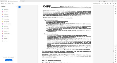
Update #2 - regardless of when i plug in the usb keyboard bit - no luck with getting the 486 mini system to respond to the keyboard requests. It simply refuses to acknowledge the presence of the pico, even when using the known working usb keyboard (the one that worked with the p4 and this pico). It could just be a weird quirky effect of this ps/2 keyboard controller (CS4041 CHIPS) on this specific system - the following extract of the datasheet may give some clues - but i'm really not sure.
Just found the batch of Bi-Directional Logic Level Converters i ordered a while ago for this.... undid my non-working version with pull ups and replaced it with the schematic for the ps2x2pico and ...
...SUCCESS!!!!
Notable differences:
- the mini 486 is now receiving commands / button presses!! no more keyboard errors (wahoo!)
- The previously incompatible usb keyboard now works and is working very well (leds like caps lock are lighting up too)
- The ps2x2pico version is much easier to build (with just 1 extra a wire for the 5v, the logic level converter is nicely aligned to the pico pins)
- Is much cleaner looking
- provides mouse and keyboard support (=more flexibility).
This is great, i can now use any modern usb keyboard and mouse on this little 486 - I can see this project is great for accessing bios menus without an old keyboard too.
I'm not sure if what i found will also impact the XT variant, is it worth retiring the other single keyboard only ps2pico version? - ps2x2pico is much much better 😀
I also didn't realize first the bi-di is a good fit for the hw interface, so I started a second repo/project.
But its easier for developing new stuff on the smaller project first and porting it afterwards.
For example the PIO and mouse support is still not finished yet in the second repo.
Also the XT version could run with only two transistors and two resistors as there are no bytes sent from the PC to the pico.
So thats why I will keep both projects.
Was reading thru that link, swapping pins isn't such a big deal (ive used a bunch of DuPont cables when I redid it to make it easier to debug anyway).
Like the idea of someone making a cheap breakout pcb too (with all the headers and sockets etc that a pico can clip into) was thinking of doing something similar if I needed to build more.
I'll continue to monitor this thread in case you need folks to help test future versions.
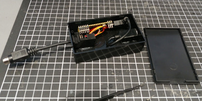
Also mounted this project in a cheap diy project box (excuse the hot glue), namely so its easier use wirhout need to grab extra cables (but also so I dont scavange the pico for other projects !)
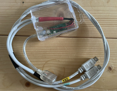
Did a ps2x2pico build this week and it works great. I cheaped out on the case, and re-used a MicroUSB OTG cable I already had. That plastic case is one I had sitting around, but I could replace that in the future with something smaller and more elegant- I wanted to put it into a case ASAP to reduce the pull on the soldered PS/2 wires. Hot glue for the win!
The PS/2 cable used is a new male-male cable I ordered off Amazon and cut in half, one half for mouse and one half for keyboard.
With a Logitech Unifying receiver I get keyboard and mouse working without having to use a USB hub.
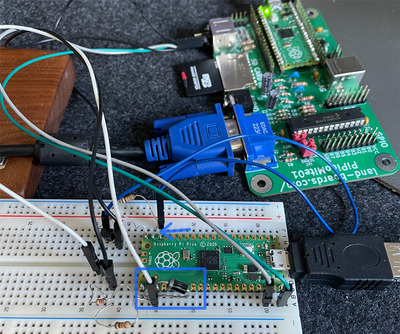
I currently have the whole thing put together on a breadboard. It didn't work initially. After some tests, I figured out to remove the Zener diode between GPIO14 and Ground. The other one from GPIO17 to Ground is still in place.
After removing it, everything worked immediately. Now I'm concerned that I might face issues with overvoltage later on.
In the picture, you can see my setup. 😉 Inside the rectangle is the Zener diode from GPIO 17 to Ground, and where the arrow is pointing, I removed it. In the end, the ps2pico is supposed to connect my Apple keyboard to a PICOMITEVGA. 😀
On the VBUS, there is pretty much exactly 5 volts. If I measure GPIO 14 to Ground or even GPIO 17, it's 0.5?!?! Whether the Zener diode is connected or not. Maybe I'm doing something wrong or I assembled it incorrectly. The Zener diodes are 3.6V 5W.
When I place a 10K resistor between GPIO 14 and Ground, everything still works.
Does anyone have any ideas? Should I just leave it or is something "wrong", even though it works without the diode?