VOGONS


Tick tock

Topic actions

First post, by SirNickity

User metadata
Rank Oldbie
Rank
Oldbie

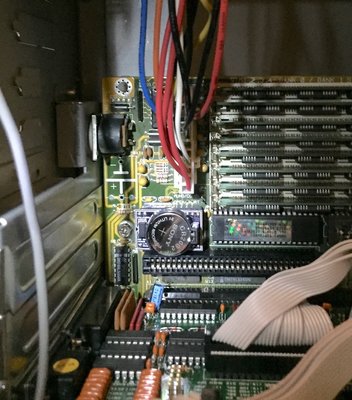
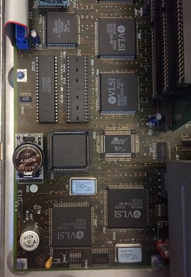
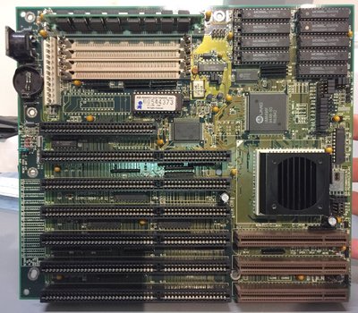
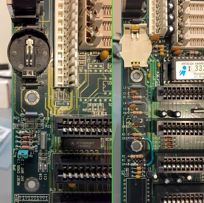
My 386DX/40 motherboard has a dead RTC module. You know the one -- Dallas DS1287, encapsulated in plastic, dead battery... Well, that caused all sorts of havoc.

Not just the obvious need to reset the clock and hard drive parameters every time I power on the computer, but despite the fact that I fix the floppy drive settings every time, when I get to DOS, it's back to some kind of hardware default setting. Drive A: is supposed to be a 5.25" 1.2MB, and B: is a 3.5" 1.44MB. But DOS can't read nor write a HD floppy, and Norton SysInfo shows the drive inventory as 2x 5.25" 360KB.

This was really cramping my style, as the SCSI card I recently bought for this PC (Adaptec AHA-1540CF) kept hanging the boot process due to a resource conflict, and the only way to fix that is with the SCSI-Select utility that I had on a floppy disk... that I couldn't read due to the BIOS settings. Can't just toss it on a ZIP disk or CD, because both those drives are SCSI, and thus inaccessible. 😒

That RTC module's gotta go.

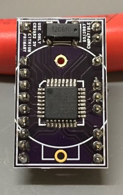
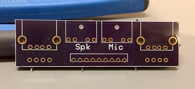
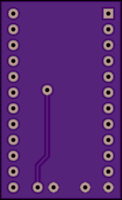
It turns out Maxim has current-model parts, like the DS12885 -- a QFP-32 surface mount part that uses an external 32kHz crystal and lithium battery. These are backward-compatible (or, I've heard, usually compatible) with the original DS1285/DS1287 parts. So, I created an adapter board:

clock2-brd1.png
Filename
clock2-brd1.png
File size
28.71 KiB
Views
1349 views
File license
Fair use/fair dealing exception
clock2-brd2.png
Filename
clock2-brd2.png
File size
16.92 KiB
Views
1349 views
File license
Fair use/fair dealing exception

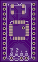
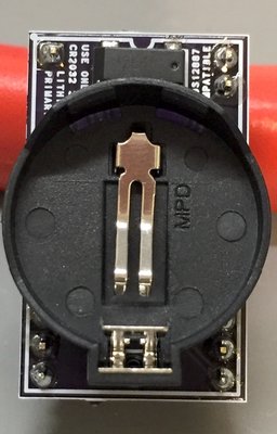
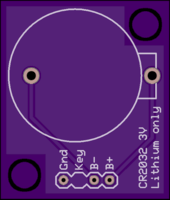
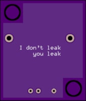
... and an external CR2032 coin cell holder:

clock-brd1.png
Filename
clock-brd1.png
File size
22.94 KiB
Views
1349 views
File license
Fair use/fair dealing exception
clock-brd2.png
Filename
clock-brd2.png
File size
11.54 KiB
Views
1349 views
File license
Fair use/fair dealing exception

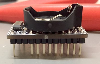
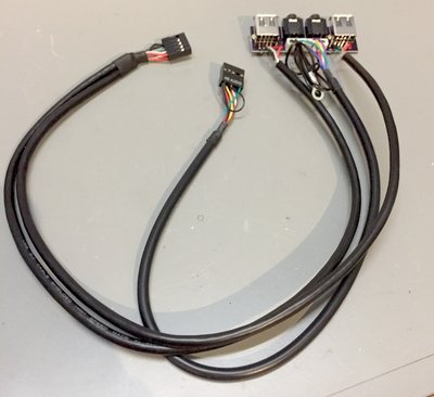
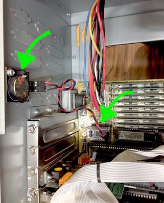
I used header connector parts from FrozenCPU and some 24AWG stranded wire from a local electronics supply shop and created a cable. Here's the end result:

clock-installed.jpg
Filename
clock-installed.jpg
File size
273.76 KiB
Views
1350 views
File license
Fair use/fair dealing exception

It took a couple tries. The first problem was a simple footprint issue. Apparently, it's not possible to get perfect PCB layouts on the first try, ever. The holes for all the header pins needs to be a step larger, so I had to clip the ends of the pins off and basically just tack them to the bottom of the board through the hole. Not ideal, but it's solid enough.

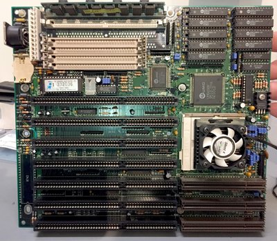
The second issue was a tiny, hardly visible solder bridge between the Reset and Data Strobe pins that kept the board from POSTing. I thought I was out of luck, but eventually noticed the bridge and, once fixed, it fired right up and FINALLY saved my settings! The floppy drives are now properly detected, SCSI card settings fixed, and Day of the Tentacle installed from CD! 😁

If anyone needs one of their own, I'm happy to publish the (fixed) Gerbers and BOM.

Reply 1 of 14, by retardware

User metadata
Rank Oldbie
Rank
Oldbie

Cool thing!
I guess this could be very helpful for many vogons!

Maybe it would be a good idea to put as many boards onto a Gerber file as possible on a 10x16 (or similar standard size) board and order a board at a PCB manufacturer, if enough vogons preorder boards.

Reply 2 of 14, by feipoa

User metadata
Rank l33t++
Rank
l33t++

There was another member here who made a Dallas 12887 replacement in which the battery mounted onto the module itself. I spent 5 minutes looking for the link, but I can't seem to find it. I must be missing the right keyword. If I can remember which computer I have my unit it, I'll take a photo.

Here it is: Re: Possible DS12887 drop-in replacement

From OSH Park: https://oshpark.com/shared_projects/NwcVatSK

Plan your life wisely, you'll be dead before you know it.

Reply 3 of 14, by Anonymous Coward

User metadata
Rank l33t
Rank
l33t

This is pretty nice.
A repalcement for the DS1387 would be nice too, but I doubt there is a replacement chip for that one.

"Will the highways on the internets become more few?" -Gee Dubya
V'Ger XT|Upgraded AT|Ultimate 386|Super VL/EISA 486|SMP VL/EISA Pentium

Reply 5 of 14, by SirNickity

User metadata
Rank Oldbie
Rank
Oldbie

Oh, hey, that integrated one is probably better since it's a single-board solution. 😀 I'll fix the holes on mine and publish it anyway, for those that might prefer an external battery, such as AAs. The chip claims to "guarantee" protection against reverse-charging, so any source of ~3V would work fine. Do not use a protection diode.

While I'm thinking of it, the BOM is thusly (with Digikey part numbers, and qty 1 price at the moment):

Maxim DS12885T+ -- TQFP-32 RTC (DPN# DS12885T+-ND, $8.93)
ECS ECS-.327-6-17X-C-TR -- 32.768kHz crystal, 6pF load capacitance, 50k ESR (DPN# XC2129CT-ND, $0.70)
MPD BS-7 -- CR2032 coin cell holder (DPN# BS-7-ND, $0.98)
0.1" male header pins of your choosing, e.g. Sullins PRPC040SAAN-RC, 40-pin breakaway (DPN# S1011EC-40-ND, $0.66)

Reply 6 of 14, by SirNickity

User metadata
Rank Oldbie
Rank
Oldbie
retardware wrote:

Maybe it would be a good idea to put as many boards onto a Gerber file as possible on a 10x16 (or similar standard size) board and order a board at a PCB manufacturer, if enough vogons preorder boards.

I'm not sure how it goes for those outside of the US, but OSH Park is really the ideal solution for things like this. Someone can publish their project, and you can order as many as you want (min. qty. is 3), at any time you want. No need for a middle-man or group buy. For a tiny board like this, it only costs a couple bucks all-in. I can't imagine it would be much (if any) cheaper to do a small-batch run and distribute them individually. Maybe it would be cheaper for someone in Europe to order a few copies and mail them to other Europeans, I dunno.

Reply 7 of 14, by dionb

User metadata
Rank l33t++
Rank
l33t++

A gentleman in France is already selling single-PCB DS12887-replacements with similar concept on a popular auction site. I bought one to test and am pretty happy with it.

Reply 8 of 14, by feipoa

User metadata
Rank l33t++
Rank
l33t++
dionb wrote:

A gentleman in France is already selling single-PCB DS12887-replacements with similar concept on a popular auction site. I bought one to test and am pretty happy with it.

Care to upload a photo?

Plan your life wisely, you'll be dead before you know it.

Reply 9 of 14, by SirNickity

User metadata
Rank Oldbie
Rank
Oldbie

Finally revisited the RTC replacement PCB. I decided to take a queue from some of the comments here and integrate the coin cell holder. I still have a copy of this project with the pins for external batteries, but in reality, it's just a lot more convenient to use CR2032s everywhere.

So here's the new PCB. First step is to solder in the RTC chip, 32kHz crystal, and the pins.

RTC-PCB1.jpg
Filename
RTC-PCB1.jpg
File size
219.49 KiB
Views
975 views
File license
Fair use/fair dealing exception

Then, add the coin cell holder on top.

RTC-PCB2.jpg
Filename
RTC-PCB2.jpg
File size
185.8 KiB
Views
975 views
File license
Fair use/fair dealing exception

And presto, RTC sammich.

RTC-PCB3.jpg
Filename
RTC-PCB3.jpg
File size
184.42 KiB
Views
975 views
File license
Fair use/fair dealing exception

Reply 10 of 14, by SirNickity

User metadata
Rank Oldbie
Rank
Oldbie

I replaced the previous version in my 386DX/40, since the pins were only tacked onto the bottom surface of the PCB. This one has large enough holes so the pins can actually go through the PCB. 😉

RTC-386.jpg
Filename
RTC-386.jpg
File size
204.29 KiB
Views
971 views
File license
Fair use/fair dealing exception

And now, let's try to get that PS/2 Model 30 - 286 running. I probably should've used different (round?) pins, because this socket is TIGHT. Maybe I just need to replace the socket. For now, it's not fully seated, but it's not going anywhere.

RTC-PS2.jpg
Filename
RTC-PS2.jpg
File size
252.35 KiB
Views
971 views
File license
Fair use/fair dealing exception

SUCCESS!! After locating the proper startup disk image online, it finally boots without errors 161 and 163!

Attachments

  • RTC-PS2OK.jpg
    Filename
    RTC-PS2OK.jpg
    File size
    133.96 KiB
    Views
    971 views
    File license
    Fair use/fair dealing exception

Reply 11 of 14, by SirNickity

User metadata
Rank Oldbie
Rank
Oldbie

Since I was ordering from OSH Park anyway, I put together a replacement front panel PCB for my Antec VSK case.

I really like this case. It was about $35 locally, without a PSU. It's definitely not built like a tank, but it seems the corners cut were reasonable compromises. Everything fits nicely and it looks pretty smart.

However, new cases all ship with USB 3.0 now, which obviously uses a different header connector than the USB 1.x/2.0 headers on retro motherboards. I have an Asus TUSL2-M installed in this case, with a Pentium III Tualatin 1.0GHz processor -- definitely not USB 3.0. I don't really like cluttering up the insides with adapters, so I ordered some USB jacks and designed a replacement board.

VSK-PCB.jpg
Filename
VSK-PCB.jpg
File size
110.44 KiB
Views
957 views
File license
Fair use/fair dealing exception

I bought some USB header extensions from Ebay and chopped off the male end, then soldered it directly to the PCB.

VSK-Wired.jpg
Filename
VSK-Wired.jpg
File size
110.68 KiB
Views
957 views
File license
Fair use/fair dealing exception

Fits like a glove!

VSK-Case.jpg
Filename
VSK-Case.jpg
File size
168.63 KiB
Views
957 views
File license
Fair use/fair dealing exception

Another completed build. 😀 Well, it's still waiting on a Plextor DVD/CD drive to show up... So almost complete.

Attachments

  • VSK-Installed.jpg
    Filename
    VSK-Installed.jpg
    File size
    219.53 KiB
    Views
    957 views
    File license
    Fair use/fair dealing exception

Reply 13 of 14, by SirNickity

User metadata
Rank Oldbie
Rank
Oldbie

Well, I have no interest in getting in the kits business. 😀 But, I'm happy to make it available for anyone who's interested in making their own. If anyone happens to have an online store and wants to carry them (or whatever), you have my blessing.

OSH Park: https://oshpark.com/shared_projects/EfNaK3A6

The BOM was posted above. I'll attach a ZIP file with the Gerbers and the original project file. I used Robot Room's Copper Connection to design the PCB. It has since been consumed by Express PCB, but there may be an old link out there somewhere.

Attachments

  • Filename
    DS1287 Retrofit AIO.zip
    File size
    15.73 KiB
    Downloads
    39 downloads
    File license
    Fair use/fair dealing exception

Reply 14 of 14, by SirNickity

User metadata
Rank Oldbie
Rank
Oldbie

Another update in the saga of vintage time-keeping. This time, I'm working on two 486 motherboards that had rechargeable barrel batteries. I wanted to convert these to use CR2032 coin cells as well. This isn't a drop-in replacement -- the coin cells aren't rechargeable and thus need some minor circuit hacks to avoid damaging anything.

First victim uh, subject is a Chaintech 4ULD.1:

mb-486-chaintech-4uld.jpg
Filename
mb-486-chaintech-4uld.jpg
File size
602.02 KiB
Views
818 views
File license
Fair use/fair dealing exception

The second is an Aquarius MB-4DUVC mk 1. This is the board I'm using in my current 486 DX/2 - 66MHz build:

mb-486-aquarius-mb4duvc.jpg
Filename
mb-486-aquarius-mb4duvc.jpg
File size
655.89 KiB
Views
818 views
File license
Fair use/fair dealing exception

Both of these had a similar circuit, where the battery would run through a small-value resistor, a protection diode, and then appear on one of the pins on a CMOS configuration jumper. Placing the jumper on pins 2-3 would connect the internal battery to the CMOS, while placing the jumper on pins 3-4 would clear the CMOS settings.

The problem is that the original circuit would also connect the battery to the +5V rail via (something like) a 150-ohm resistor and another protection diode. This needed to go. However, simply disconnecting this part of the circuit would mean the CMOS and RTC were always running on battery, potentially draining the coin cell more quickly. So, I wanted to modify the circuit to allow the system to run from the PSU when powered on, and from the battery otherwise.

The modified circuit looks like this, where gray is a removed component and red is an added component:

MBRTCFix.png
Filename
MBRTCFix.png
File size
5.65 KiB
Views
817 views
File license
Fair use/fair dealing exception

Finally, a close-up of the rework:

mb-rtc-fix.jpg
Filename
mb-rtc-fix.jpg
File size
276.35 KiB
Views
818 views
File license
Fair use/fair dealing exception

Luckily both boards had multiple footprints where the barrel battery goes. Each had a 20mm spacing that is compatible with standard coin cell holders. Unfortunately, the Aquarius board did not provide ample room for the holder itself, so I had to find a slightly smaller one. Naturally, I forgot to order the required cap that actually holds the coin cell in place, so I'm hoping everything still fits when I finally get around to putting it together.

But there it is. Both boards are now ready to go for a couple decades free of amnesia. I think that concludes all the outstanding issues I have with RTCs.