VOGONS


First post, by charly2k18

User metadata
Rank Newbie
Rank
Newbie

Hello, i'm not new to the forum, but I din't write any post since today 😀. I'm from Catalonia so english maybe not perfect but I will try to write the best I can!.

Now, the problem:

I have a Forex 386DX-40 cache motherboard that it doesn't work at all, no POST, no BEEPS.. nothing 🙁. I uploaded a video to Youtube in order you see the problem it has.

Link to Stason info:

https://stason.org/TULARC/pc/motherboards/M/M … -386-CACHE.html

Link to Youtube:

https://youtu.be/QHXcbHHSskc

When I click the powerbutton, there is a strange noise coming from speaker. It doesn't have any regular patron so it is totally random and there is absolutely no difference if I disconnect RAM or disconnect VGA card. Resistors visually are all ok too..

There are two replaced tantallium caps because two of them burnt time ago.

If we look at back of the board, there is a trace without copper protection, but continuity test is ok at that point.

I measured the PSU and the voltages are OK

P9: PIN 1: Ground
PIN 2: Ground
PIN 3: -5.034
PIN 4: 4.877
PIN 5: 4.878
PIN 6: 4.878

P8: PIN 1: Ground
PIN 2: Ground
PIN 3: -12.125
PIN 4: 12.730
PIN 5: 4.877
PIN 6: 4.940

Link to images:

https://imgur.com/a/ujCnm5z

BIOS apparently is OK because it runs perfect with PCEM (TL866 dumped image).

Please, can you help me? If you need more images or something else, I can upload more. ah!, one more thing, I'm not an expert in electronics, so my knowledge is very limited, but I will try to understand anything you write 😀.

Thanks in advance guys!!

Reply 1 of 35, by Deunan

User metadata
Rank Oldbie
Rank
Oldbie

RDY led is not lit, which is strange. Remove VGA card (Is that a Trident TVGA8900C? Decent VGA for a 386 system.) and try again. Remove RAM and try again. Put a jumper on JP2 middle pins (2-3) and try again.
I wonder why it has 40MHz CPU if the clock generator is only 66MHz. Also, someone replaced a few of the tantalum caps near the power connector - probably the +12V and -12V ones. These like to explode and/or catch on fire so that's probably what happened.

Reply 2 of 35, by charly2k18

User metadata
Rank Newbie
Rank
Newbie
Deunan wrote:

RDY led is not lit, which is strange. Remove VGA card (Is that a Trident TVGA8900C? Decent VGA for a 386 system.) and try again. Remove RAM and try again. Put a jumper on JP2 middle pins (2-3) and try again.
I wonder why it has 40MHz CPU if the clock generator is only 66MHz. Also, someone replaced a few of the tantalum caps near the power connector - probably the +12V and -12V ones. These like to explode and/or catch on fire so that's probably what happened.

Hi Deunan, thanks for your help! 😀. I have done what you told me but the problems persist 😒. Regarding the VGA.. yes!, it's a Trident TVGA8900C, not a fast one but very competitive in those years! hehe. Replaced tantalum caps have 10 uF 25 specs and the other ones, 10 uF 16 specs. Don't know who change them... ah, and I replaced clock generator with another working one. It seems that this motherboard has a serious problem.

Link to new video:

https://youtu.be/e9UglxVku7M

Reply 3 of 35, by Deunan

User metadata
Rank Oldbie
Rank
Oldbie

Hm, no effect huh. Since you're able to replace the clock gen now I assume it's socketed? Is it inserted in correct orientation (don't just try to rotate it, might get damaged by reversed voltage!) - double check the PCB markings to be sure. I can't see that detail on YT video.
This mobo seeems to route the CMOS/RTC power all the way from battery in the back to this MORSE chip in front. There's a jumper here, JP202, used to clear CMOS. Check if you get +5V on it when you power up - with, and without the jumper on JP2 I mentioned earlier. Actually the voltage might be lower but the point is: if you get at least 3V here without the JP2 jumper then you probably don't need it.

In general if there is no codes and no reaction at all then the CPU isn't running, or the BIOS image it's getting to execute is corrupted. If the BIOS ROM itself is OK then that leaves you with either a socket/trace problem or one of the main chips is busted. I assume you don't have an oscilloscope? Then build yourself a probe like this:

RBl9hAG.png

Use 2 of the LEDs in series instead of 1, this way they won't glow a bit even when the tip is not connected. Test it by touching the tip to ground and +5V, one color bank of the LEDs should come on - if so, it works OK.

With that probe power the mobo and touch each pin of the BIOS ROM with the tip (just be careful not to make a short), see what the LEDs do. Write it all down, report back.

Reply 6 of 35, by charly2k18

User metadata
Rank Newbie
Rank
Newbie

Hi again!. Just to be sure that I am doing it correctly and before continuing with the tests, would this circuit be correct? the leds are of different color: green +5 and red GND. These days I will put the results! 😀

Attachments

  • prueba.png
    Filename
    prueba.png
    File size
    53.03 KiB
    Views
    1320 views
    File license
    Fair use/fair dealing exception

Reply 8 of 35, by Deunan

User metadata
Rank Oldbie
Rank
Oldbie
charly2k18 wrote:

Hi again!. Just to be sure that I am doing it correctly and before continuing with the tests, would this circuit be correct? the leds are of different color: green +5 and red GND. These days I will put the results! 😀

It's OK, though as I've mentioned with just 1 LED per color you will get them to glow a bit (both at once) even when the probe tip is not connected. This can be fixed by having 2 LEDs of each color in series. But you can start with this circuit and see how it works for yourself.

Also, connect a reset button to the mobo. Use it after you powered the system on to make sure it's a not a reset signal issue. You should see the reset LED on the test card change state as you press the button.

Reply 9 of 35, by charly2k18

User metadata
Rank Newbie
Rank
Newbie

Ok guys, I'm a little busy these days but finally here are the results of the tests:

First, I've measured the voltage on jumper 202:

- JP2 closed: 4.811 V
- JP2 open: 4.809 V

Second test with the reset switch: when I close the jumper, reset LED is ON on the test card and when the jumper is open, LED test card is OFF, so I suppose that it's working.

And finally the results with the led circuit (which I think I made correctly). There are two columns because when I was doing the tests, sometimes all the LEDs were illuminated. Please see the attached file below and its legend.

We continue with the Fore(X) "files" motherboard... 😉

Attachments

Reply 10 of 35, by retardware

User metadata
Rank Oldbie
Rank
Oldbie

No LED illumination observable on pin 11-13?
Not even the faintest?

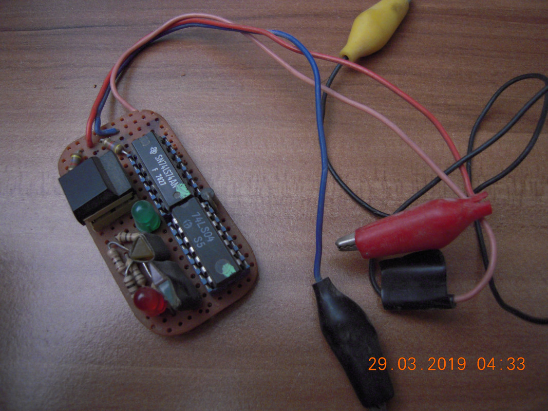
By the way, for such things I made a small tool long time ago. I think I still have the schematics in my paper files, would fit on a breadboard. Will post when I find it.

DSCN9641.jpg

The round LEDs do what your LEDs do.
The red/green arrow leds show if a level change has happened (hi->lo, lo->hi).
The yellow led shows if a pulse has been sent (two subsequent level changes)
The button resets the flipflops.

Reply 12 of 35, by retardware

User metadata
Rank Oldbie
Rank
Oldbie

Very good!
Seems like processor is running.
Then it would be interesting to find out what was different when the address lines were these on the second row.
Can you reproduce that or is it totally random?

Reply 13 of 35, by Deunan

User metadata
Rank Oldbie
Rank
Oldbie
charly2k18 wrote:

On pins 11-13, the RED LEDS light up, although very faintest.

The good news is you get a lot of activity on pins 20 and 22 so the chip is being addressed - most likely CPU clock is running and it's fetching code from BIOS. But since it doesn't work the reads return wrong values and either the CPU enters infinite loop or faults on invalid opcode.

Let's say it was an intentional dead loop, the shortest variant would be something like this
here: jmp here
This ends up as 2-byte machine code EBFE, so mostly ones and only 1 or 2 lowest address bits would change. And what do you know, your tests seems to get mostly high level on data pins and data pins A0 and A1 show a lot of activity, others not much at all. This is just an educated guess, obviously.

Please inspect all ISA slots and make sure there are no bent contacts being shorted to one another. You mentioned TL866 so I assume you have EPROM burner? Do you have a 5V FLASH or EEPROM chip with 28 pins? Preferably a direct replacement for 27C512 (which are not that common) but a '256 will do as well. Even a '128 might but you'll have to mod it with wires so not recommended.

Reply 14 of 35, by charly2k18

User metadata
Rank Newbie
Rank
Newbie

I don't remember that there was any short or bent contacts, but, I will double check it again and make sure (not at home now). Regarding the TL866, you are correct Deunan, I have one and a 27C512 replacement that I bought a few months ago so we're in luck 😀. Thanks all for your help!

Attachments

  • TL866.jpg
    Filename
    TL866.jpg
    File size
    1.48 MiB
    Views
    1163 views
    File license
    Fair use/fair dealing exception

Reply 15 of 35, by Deunan

User metadata
Rank Oldbie
Rank
Oldbie

Great, program the binary file I've attached to the chip and put it in place of the BIOS. Remove all cards except the test card and boot the system. Do you get a code displayed now?

Attachments

  • Filename
    boot.7z
    File size
    237 Bytes
    Downloads
    46 downloads
    File comment
    BOOT ROM #1
    File license
    Fair use/fair dealing exception

Reply 16 of 35, by charly2k18

User metadata
Rank Newbie
Rank
Newbie

Ok, Deunan, I programmed the binary file that you attached to the replacement BIOS chip, but unfortunately there was no difference. Meanwhile, I have measured the voltages on the ISA port, as well as the tests with the LED circuit. I hope it helps!

ISA Bus pins (from Wikipedia):

https://upload.wikimedia.org/wikipedia/common … SA_Bus_pins.svg

Attachments

  • ISA voltages.png
    Filename
    ISA voltages.png
    File size
    40.17 KiB
    Views
    1113 views
    File license
    Fair use/fair dealing exception
  • IMG_20190331_003144.jpg
    Filename
    IMG_20190331_003144.jpg
    File size
    710.26 KiB
    Views
    1113 views
    File license
    Fair use/fair dealing exception

Reply 17 of 35, by Deunan

User metadata
Rank Oldbie
Rank
Oldbie

It didn't work? That complicates things.
Okay, another approach. Burn this file as BIOS, replace, boot. Ignore the test card, probe the BIOS chip pins again and write down the LED behaviour.

Attachments

  • Filename
    boot.7z
    File size
    206 Bytes
    Downloads
    40 downloads
    File comment
    BOOT ROM #2
    File license
    Fair use/fair dealing exception

Reply 18 of 35, by feipoa

User metadata
Rank l33t++
Rank
l33t++

You can take a look at my similar thread on such troubleshooting here: https://www.eevblog.com/forum/repair/how-to-t … n-oscilloscope/

I have 3 defective 386 boards. On one board, it turned out to be a lead on a QFP chip which wasn't making contact. It was not obvious by looking at it. I had to move each lead with a sewing needle or scalpel. Another dead board was due to a through-hole solder point which was making marginal contact. On the third - I forget what the issue was. Its in the thread though. I think there may have been a piece of metal shrapnel shorting some leads?

Plan your life wisely, you'll be dead before you know it.

Reply 19 of 35, by charly2k18

User metadata
Rank Newbie
Rank
Newbie

Very thanks to all for your help and your time!

Feipoa, I have revised all the contacts on the QFP chips and apparently all are OK 😒, but I will revise all the through-hole solder point even though it seems are all ok too. If this can help, If I touch the chips on the board, all aren't hot, but not cold too, the only one that is hot but not much is the CPU, it doesn't burn.

Deunan, the BIOS replace bin didn't help again 🙁. Here are the results of the test:

Attachments