VOGONS


First post, by pmuench

User metadata
Rank Newbie
Rank
Newbie

Hi Everyone!

I recently started to act on my longtime dream to get into retro hardware and relive my old 386 gaming days when I found a bunch of old hardware in a closet at work. So, naturally Vogons is the place to be 😊

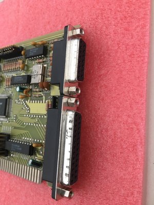
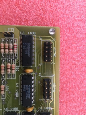
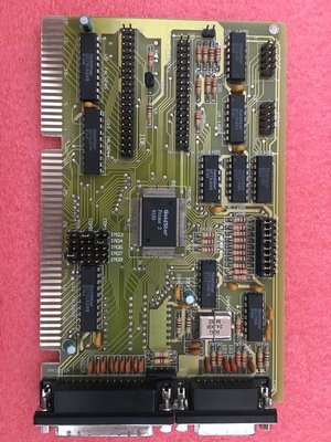
I got a 386 running with 8 Megs of RAM, a Tseng ET4000, an Opti/Crystal based sound card, a CF adapter and a Gotek Floppy Emulator. On Ebay, I found a combo offer of a Goldstar Prime based controller card and a networking card with an XTIDE Rom.

Now all of this runs great, with one small problem: I made the mistake of buying those two cards despite the fact that the brackets were missing. So right now, I'm not able to attach a mouse to the PC 😢

I've got some other serial brackets, none of which have the right pinouts, obviously, but I'd be willing to sacrifice one of them, rearranging the wiring to fit the controller, but I cannot find any info on the header pinout on the board.

So there's my question: Does anybody have a diagram of the pinout, or might be willing to create one with his/her bracket and a multimeter? 😊 I'd be forever grateful for that!

Best regards,
pmuench

Attachments

Reply 1 of 2, by GigAHerZ

User metadata
Rank Oldbie
Rank
Oldbie

As you can see, it is numbered like this:
1 3 5 7 9
2 4 6 8 10

Another option would be
1 2 3 4 5
6 7 8 9 10

Both are "standards" but you do need appropriate serial port or modify one into appropriate one.

http://lmgtfy.com/?q=serial+pinout

"640K ought to be enough for anybody." - And i intend to get every last bit out of it even after loading every damn driver!

Reply 2 of 2, by pmuench

User metadata
Rank Newbie
Rank
Newbie

A well, you brought me on the right track.
First of all, I didn't think that the numbering on the board would actually correspond to the numbering of the pins on the db-9 connector. Well, they do.

I had 2 brackets lieing around:
One following the second pattern, that fit on the header, because it was unkeyed, but obviously didn't work.
A second bracket didn't fit because it was keyed. I took a look at the card and saw that one of the header pins also was not connected, and at first glance, it seemed to be pin 9. This did not correspond with the missing hole on the connector, so I thought that bracket also would not work.

I was wrong: I took my multimeter and checked, and it was actually pin 10 that was not connected. I bent it to the side (Yes I know 😅) and tested it, and - lo and behold - it works! 😊

So, thanks a lot!

GigAHerZ wrote:
As you can see, it is numbered like this: 1 3 5 7 9 2 4 6 8 10 […]
Show full quote

As you can see, it is numbered like this:
1 3 5 7 9
2 4 6 8 10

Another option would be
1 2 3 4 5
6 7 8 9 10

Both are "standards" but you do need appropriate serial port or modify one into appropriate one.

http://lmgtfy.com/?q=serial+pinout